Table of Contents
Advertisement
Quick Links
Operation, Repair, and Parts
™
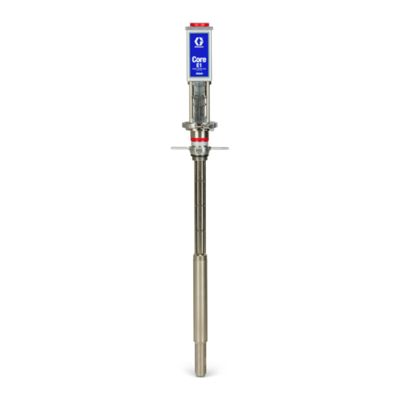
Core
E1 Electric Transfer Pump
For use with polyurethane foam, polyurea, and similar non-flammable materials. For use
®
with Reactor
3 Systems only. For professional use only.
Not approved for use in explosive atmospheres or hazardous (classified) locations.
See page 3 for model information.
315 psi (2.17 MPa, 21.7 bar) Maximum Fluid Working Pressure
Important Safety Instructions
Read all warnings and instructions in this
manual before using the equipment.
Save these instructions.
3A8503C
EN
Advertisement
Table of Contents

Subscribe to Our Youtube Channel
Related Manuals for Graco Core E1


Summary of Contents for Graco Core E1
- Page 1 Operation, Repair, and Parts 3A8503C ™ Core E1 Electric Transfer Pump For use with polyurethane foam, polyurea, and similar non-flammable materials. For use ® with Reactor 3 Systems only. For professional use only. Not approved for use in explosive atmospheres or hazardous (classified) locations. See page 3 for model information.
-
Page 2: Table Of Contents
Flush Before Using Equipment ... . . 15 ® Graco Extended Warranty for Reactor Pressure Relief Procedure ....15 Components . -
Page 3: Models
157785 217382 247616 210866 162453 Core E1 Transfer 26D000 Pump Controller ✓ (TPC) 26D004 Core E1 Pump Two Core E1 Pumps 26D005 with TPC ✓ Carbon Two Core E1 Pumps 26D006 Steel with TPC and Fluid ✓ ✓ ✓ Two Core E1 Pumps... -
Page 4: Warnings
Warnings Warnings The following warnings are for the setup, use, grounding, maintenance, and repair of this equipment. The exclamation point symbol alerts you to a general warning and the hazard symbols refer to procedure-specific risks. When these symbols appear in the body of this manual or on warning labels, refer back to these Warnings. Product-specific hazard symbols and warnings not covered in this section may appear throughout the body of this manual where applicable. - Page 5 Warnings WARNING PRESSURIZED EQUIPMENT HAZARD Fluid from the equipment, leaks, or ruptured components can splash in the eyes or on skin and cause serious injury. • Follow the Pressure Relief Procedure when you stop spraying/dispensing and before cleaning, checking, or servicing equipment. •...
-
Page 6: Important Isocyanate (Iso) Information
Important Isocyanate (ISO) Information Important Isocyanate (ISO) Information Isocyanates (ISO) are catalysts used in two component materials. Isocyanate Conditions Spraying or dispensing fluids that contain isocyanates creates potentially harmful mists, vapors, and atomized particulates. • Read and understand the fluid manufacturer’s warnings and Safety Data Sheets (SDSs) to know specific hazards and precautions related to isocyanates. -
Page 7: Material Self-Ignition
Important Isocyanate (ISO) Information Material Self-Ignition NOTE: The amount of film formation and rate of crystallization varies depending on the blend of ISO, the humidity, and the temperature. Foam Resins with 245 fa Blowing Agents Some materials may become self-igniting if applied too thick. -
Page 8: Typical Installation
Typical Installation Typical Installation Typical Installation without Circulation (ISO) (RES) . 1: Typical Installation without Circulation NOTE: See page 10 for required components. Ref. Description Proportioner Agitator Air Supply Line Fluid Supply Lines Transfer Pumps (other items purchased separately) Agitator Desiccant Dryer Bleed Lines Waste Containers... -
Page 9: Typical Installation With Circulation
Typical Installation Typical Installation with Circulation (ISO) (RES) . 2: Typical Installation with Circulation Ref. Description Proportioner Agitator Air Supply Line Fluid Supply Lines Transfer Pumps (other items purchased separately) Agitator Desiccant Dryer Circulation Lines NOTE: See page 10 for required components. 3A8503C... -
Page 10: Typical Pump And Transfer Pump Controller Installation
Typical Installation Typical Pump and Transfer Pump Controller Installation . 3: Typical Pump and Transfer Pump Controller Installation Ref. Description Transfer Pump Desiccant Dryer Fluid Drain Valve (required) Bung Adapter Grounded Fluid Hose Pump Fluid Inlet Pump Fluid Outlet, 3/4 npt(f) Electric Motor Cable Power Switch Transfer Pump Controller... -
Page 11: Typical Multiple Pump Lowers Installation
Typical Installation Typical Multiple Pump Lowers Installation NOTE: Material drums used are either two A side material drums, or two B side material drums. To Reactor ti40375a . 4: Typical Multiple Pump Lowers Installation Ref. Description Return Tube Kit (not included) Multiple Pump Lower Fluid Kit (not included) Grounded Fluid Hose (not included) E1 Motor... -
Page 12: Installation
Installation Installation Grounding surface, such as paper or cardboard, which interrupts grounding continuity. To maintain grounding continuity when flushing or The equipment must be grounded to reduce the risk relieving pressure: Hold metal part of the spray gun of static sparking. Static sparking can cause fumes firmly to the side of a grounded metal pail, then trigger to ignite or explode. - Page 13 Installation Connect the CAN Cable to the TPC 2. Remove the ground screws (green) from the grounding standoffs. NOTE: The CAN cable allows the TPC to communicate with the Reactor and provides low voltage power to the TPC. It does not provide power to run the electric motor.
-
Page 14: Pump Setup
Installation Pump Setup Install the Pump 1. Lubricate the o-ring on the outside of the bung adapter (AF) and screw the bung adapter securely into the bunghole (DB) of the drum. A fluid drain valve (AE) is required in your system to help reduce the risk of serious injury, including splashing fluid in the eyes or on the skin, and injury from moving parts when you are adjusting or... -
Page 15: Operation
Operation Operation Pressure Relief Procedure NOTICE Do not operate if the pump lower and electric motor are not properly coupled together or without the clamp installed and tightened. Damage to the equipment could occur. Flush Before Using Equipment This equipment stays pressurized until pressure is manually relieved. -
Page 16: Changing Material Drums
Operation Changing Material Drums 3. Open the electric motor access door (DD). NOTE: If the height of your ceiling or trailer prohibits removal of the pump, remove the electric motor before swapping out material drums. Remove the Pump 1. Follow the Pressure Relief Procedure on page 15. 2. -
Page 17: Using The Electric Motor
Operation Install the Electric Motor 6. Simultaneously slide the electric motor coupler (CP) onto the button head of the pump lower and the electric motor onto the pump lower. Close the electric motor access door (DD). Never use the power cord to lift or adjust the pump. Lifting or adjusting the pump with the power cord can damage it and cause injury from electric shock. -
Page 18: Daily Startup
Operation Daily Startup Daily Shutdown 1. Follow the Shutdown procedure in your Reactor 3 1. Turn the TPC power switch (ZP) to ON. operation manual. 2. Turn the TPC power switch (ZP) to OFF. 2. Follow the Startup procedure in your Reactor 3 operation manual. -
Page 19: Pump Status Leds
Operation Pump Status LEDs The Transfer Pump Controller (TPC) uses five LEDs to communicate the current status of the pumps and TPC. The two LEDs on the top relate to the electric motor status (A on the left, B in the center). The three LEDs on the bottom right are the TPC status LEDs. -
Page 20: Troubleshooting
Clean ball and seat. shutoff in the upstroke Worn or damaged valves or seats Install repair kit. NOTE: For additional troubleshooting information, go to help.graco.com and search for E1 Transfer Pumps. Maintenance Monthly Daily Electrical connections can loosen over time due to Check the clamp nut (DN) on a daily basis and tighten if transporting equipment and normal operation. -
Page 21: Repair
Repair Repair Replace the Motor Cable 5. Disconnect the three motor wires from the three wires of the motor cable. Required Tools 6. Lift the motor cable strain relief (213) out of the groove in the motor housing. • 2.5 mm Allen wrench •... - Page 22 Repair TPC End Disassembly 3. Use a 1/8 in. or 3 mm slotted screwdriver to loosen the screws on both connectors (J1A/J2A or 1. Use a No. 2 Phillips screwdriver to loosen captive J1B/J2B) of the cable being replaced. fasteners and remove the TPC access cover (ZC). 4.
-
Page 23: Replace The Encoder
Repair Replace the Encoder Encoder Reassembly Required Tools 1. Add a drop of medium strength thread locking • 2.5 mm Allen wrench compound to the threads of the encoder (216) stem. • 3/16 in. Allen wrench 2. Use a 3/16 in. Allen wrench to install the encoder •... -
Page 24: Replace The Guide Cover
Repair Calibration 3. Remove the mounting clamp ring (206) from the tie rods (203). After replacing the encoder, the pump must be calibrated. See your Reactor 3 operation manual for the 4. Slide the guide cover (208) out of the tie rods. calibration procedure. -
Page 25: Replace The Ball Screw Assembly
Repair Replace the Ball Screw Ball Screw Disassembly Assembly 1. Follow Remove the Electric Motor on page 16. 2. Use a 3/16 in. Allen wrench to remove four Required Tools fasteners (207) from the bottom of the mounting clamp ring (206). •... - Page 26 Repair Ball Screw Reassembly NOTE: The notch in the mounting clamp ring (206) aligns with the tab on the guide cover (208) access 1. Thoroughly clean all grease and debris from the door. inside of the guide cover (208) and inside the motor shaft.
-
Page 27: Parts
Parts Parts Pump (26D004) Pump Lower Parts List Ref. Part Description Qty. 273295 PUMP, lower, et 3 25T322 ELECTRIC MOTOR 25B395 ADAPTER, bung, 2 in., EZ removal 510490 CLAMP, pump 26D216 BAND, identity, res (blue) 26D216 BAND, identity, iso (red) 3A8503C... -
Page 28: Electric Motor (25T322, 26D009)
Parts Electric Motor (25T322, 26D009) Electric Motor Parts List Ref. Part Description Qty. Ref. Part Description Qty. - - - - - WASHER, housing, 30 mm - - - - - MOTOR, electric - - - - - BEARING, thrust, roller, 30 mm - - - - - ROD, tie - - - - -... -
Page 29: Accessories
TPC (26D000) To ensure maximum pump performance, make sure all Ref. Part Description Qty. accessories are properly sized to meet your system 301 19B841 CONTROLLER, CORE E1 transfer requirements. pump 302 121004 CABLE, can, female/female 8.0 m Fluid Line 303 121055... - Page 30 Parts Return Tube Kit (not included) Multiple Pump Lowers Fluid Kit (not included) Part Description Qty. Ref. Part Description Qty. 246477 KIT, carbon steel return tube 26D219 Fluid Coupling Kit 24D106 KIT, stainless steel return tube 217382 Fluid Supply Hose (10 ft) 246978 KIT, carbon steel return tube;...
-
Page 31: Electrical Connections
Electrical Connections Electrical Connections Connectors J1A and J1B Connectors J2 and J2B Position Signal Wire Color Position Signal Wire Color Motor Output C White Encoder Power White / Violet (24 Vdc) Motor Output B Encoder Return Violet Motor Output A Black (0 Vdc) (Not Used) -
Page 32: Dimensions
Dimensions Dimensions 11.4 in. (289 mm) 3.9 in. (99 mm) 10.8 in. (269 mm) 5.1 in. 8.8 in. (129 mm) (223 mm) 0.28 in. 1.7 in. (7.0 mm) (43 mm) 3A8503C... -
Page 33: Recycling Or Disposal
Dimensions Recycling or Disposal End of Product Life At the end of a product’s useful life, recycle it in a responsible manner. California Proposition 65 CALIFORNIA RESIDENTS WARNING: Cancer and reproductive harm – www.P65warnings.ca.gov. 3A8503C... - Page 34 Dimensions 3A8503C...
-
Page 35: Technical Specifications
Technical Specifications Technical Specifications Core E1 Electric Transfer Pump Metric Maximum fluid working pressure 315 psi 2.17 MPa, 21.7 bar Maximum continuous outlet flow 4.5 gpm 17.03 lpm Pump cycles per 1 gallon (3.8 liters) Volume per pump cycle 0.034 gallons 0.128 liters... -
Page 36: Graco Extended Warranty For Reactor
With the exception of any special, extended, or limited warranty published by Graco, Graco will, for a period of twelve months from the date of sale, repair or replace any part of the equipment determined by Graco to be defective.
Need help?
Do you have a question about the Core E1 and is the answer not in the manual?
Questions and answers