Table of Contents
Advertisement
Quick Links
Repair - Parts
™
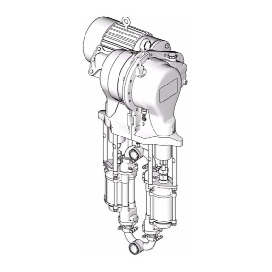
E-Flo
Circulation Pump
Durable, energy efficient piston pumps for high volume paint circulation
applications.
Important Safety Instructions
Read all warnings and instructions in this manual.
Save these instructions.
See page 3 for model information, including maximum working pressure and approvals.
Graco Inc. P.O. Box 1441 Minneapolis, MN 55440-1441
Copyright 2007, Graco Inc. is registered to I.S. EN ISO 9001
Plus Electric
311594 rev.B
ti8317a
Advertisement
Table of Contents

Related Manuals for Graco E-Flo Plus


Summary of Contents for Graco E-Flo Plus
- Page 1 Read all warnings and instructions in this manual. Save these instructions. See page 3 for model information, including maximum working pressure and approvals. ti8317a Graco Inc. P.O. Box 1441 Minneapolis, MN 55440-1441 Copyright 2007, Graco Inc. is registered to I.S. EN ISO 9001...
-
Page 2: Table Of Contents
Pressure Transducer Kit 15H876 ..15 Graco Information ......38 Pressure Sensor Calibration Information . -
Page 3: Models
Models Models E-Flo Plus Electric Circulation Pumps Check your pump’s identification plate (ID) for the 6-digit part number of your pump. Use the following matrix to define the construction of your pump, based on the six digits. For example, Pump Part No. E P 2 1 6 0 represents electric power (E), pump (P), 230/460V motor (2), sensor circuit installed (1), and 2000 cc Maxlife lower (6). -
Page 4: Warnings
Warnings Warnings The following warnings are for the setup, use, grounding, maintenance, and repair of this equipment. The exclama- tion point symbol alerts you to a general warning and the hazard symbol refers to procedure-specific risk. Refer back to these warnings. Additional, product-specific warnings may be found throughout the body of this manual where applicable. - Page 5 Warnings WARNING PRESSURIZED EQUIPMENT HAZARD Fluid from the gun/dispense valve, leaks, or ruptured components can splash in the eyes or on skin and cause serious injury. • Follow Pressure Relief Procedure in this manual, when you stop spraying and before cleaning, checking, or servicing equipment.
- Page 6 Warnings 311594B...
-
Page 7: Pressure Relief Procedure
Pressure Relief Procedure Pressure Relief Flushing Procedure • Flush before changing colors, before storing, System pressure can cause the pump to cycle unex- and before repairing equipment. pectedly, which could result in serious injury from splashing or moving parts. • Flush at the lowest pressure possible. -
Page 8: Troubleshooting
Troubleshooting Troubleshooting 1. Relieve the pressure. 2. Check all possible problems and solutions before disassembling pump. PROBLEM CAUSE SOLUTION Pump does not operate. Insufficient power supply. Verify that power supply meets require- ments. See Technical Data, page 37. No flow rate input to VFD. Select speed/flow setting. - Page 9 Troubleshooting PROBLEM CAUSE SOLUTION Pump will not prime Suction line clogged. Clear. Flush more frequently. Held open or worn ball check valves. Check and repair. Lower piston assembled with wrong nut. Use only the large, round, special nut. Excessive throat leakage. Worn piston rod or throat packings.
-
Page 10: Electrical Diagrams
Electrical Diagrams Electrical Diagrams . 1 shows components which must be installed in a . 2 shows components approved for installation in a non-hazardous location. hazardous location. . 1: System Wiring Schematic, Non-Hazardous Location Only 311594B... - Page 11 Electrical Diagrams SEE DETAIL BELOW SEE ABOVE . 2: System Wiring Schematic, Hazardous Location 311594B...
-
Page 12: Repair
Repair Repair Fluid Section 5. Using a 1-5/8 in. open-end wrench, unscrew the coupling nut (14) from the slider piston (9) and let it Complete kits are available to convert from one size slide down onto the pump piston rod. Be careful not lower to another. -
Page 13: Reassembly
Repair Reassembly 8. Ensure that the collars (13) are in place in the cou- pling nut (14). 1. See F . 4. Install the coupling nut (14) on the lower’s piston rod (PR). 9. Place a 3/4 in. wrench on the flats of the slider pis- ton (9), to keep it from turning when you are tighten- 2. -
Page 14: Slider Cylinder Rebuild Kit 15H874
Repair Slider Cylinder Rebuild Kit 15H874 Slider Cylinder Rebuild Kit 15H874 includes parts to rebuild one slider cylinder assembly. Order two kits to rebuild both slider cylinder assemblies. Use all the new parts in the kit. The kit includes manual 311599. -
Page 15: Electrical Section
Repair Electrical Section 3. Shut off electrical power to the unit. Sensor Circuit Kit 15J755 is available to add the 4. Remove two screws (12) and the cover (32). optional sensor circuit to a pump. Use all the new parts in the kit. See manual 311603. 5. -
Page 16: Pressure Sensor Calibration Information
Repair 11. See F . 7. At the pump outlet manifold (17), loosen Pressure Sensor Calibration Information the transducer nut (43) and unscrew the adapter Pressure sensor information (Pr 20.34, 20.35, and (42) from the manifold. Remove the transducer 20.36) for your system must be keyed into the Vari- (25a) from the manifold port and pull its cable out of able Frequency Drive before system start-up. -
Page 17: Pressure Transducer Calibration Procedure
Take a pressure reading from the calibration an instrument grade High Precision Pressure Trans- instrument and make a record of it. ducer, which should be installed near the E-Flo Plus pressure sensor. d. Navigate to Pr 20.35 and enter the recorded system pressure. - Page 18 Repair 311594B...
-
Page 19: Tdc Sensor Kit 15H877
Repair TDC Sensor Kit 15H877 16. Install the new gasket (33), the cover (34), and six screws (12). TDC Sensor Kit 15H877 replaces the TDC sensor. 17. Reinstall the cover (32) with two screws (12). Use all the new parts in the kit. The kit includes manual 311601. -
Page 20: Drive Section
Repair Drive Section Slider Bearing Kit 15H882 5. Place a clean rag over the top of the slider cylinder (2) to prevent debris from falling into the slider assembly during disassembly. Slider Bearing Kit 15H882 includes parts to rebuild both slider bearing assemblies. Use all the new 6. - Page 21 Repair 9. See F . 11. Rotate the crank arm (4) to allow it to 13. Slide the piston (9) and connecting rod (7) into the be removed from the output shaft (OS). cylinder (2). 10. Pull the crank arm/connecting rod/slider piston 14.
-
Page 22: Drive Linkage Rebuild Kit 15H873
Repair Drive Linkage Rebuild Kit 15H873 Drive Linkage Rebuild Kit 15H873 includes parts to rebuild one drive linkage assembly. Order two kits to rebuild both drive linkage assemblies. Use all the new parts in the kit. The kit includes manual 311598. -
Page 23: Crank Arm Kit 15H883
Repair Crank Arm Kit 15H883 Crank Arm Kit 15H883 is available. Order two kits to rebuild both crank arm assemblies. Use all the new parts in the kit. The kit includes manual 311604. Crank Arm Cover Kit 15H378 is available to replace both crank arm covers (21, 32). -
Page 24: Motor/Gear Reducer
Repair Motor/Gear Reducer Motor Removal Motor Installation • To install a NEMA 184 TC Frame electric motor, order Motor Coupler Kit 15H880. See manual 311605. 1. Relieve pressure, page 7. • To install an IEC 112M/B5 Frame electric motor, order Motor Adapter Kit 15J893. See 2. - Page 25 Repair When installing an IEC 112M/B5 Frame electric motor, ensure that the motor adapter (AP) and screws (MS) are in place before mounting the motor on the gear reducer. See F . 18. CAUTION If installing an IEC 112M/B5 Frame electric motor, ensure that the motor shaft key cannot move out of position.
-
Page 26: Gear Reducer Seal Kit 15H871
Repair Gear Reducer Seal Kit 15H871 7. Place tape over the input shaft keyway, to prevent damage to the new seal. Pack the input shaft seal cavity with Part No. 107411 Grease. Install the input Gear Reducer Seal Kit 15H871 and Output Shaft seal (109) with the lip facing in, until the seal con- Seal Tool Kit 15J926 are available. - Page 27 Repair 11. Install the two output seals (116) as follows: Remove the tools. Take three measurements 120° apart, from the surface of the seal to the a. Place tape over the output shaft keyway, to pre- face of the housing (H). The three measure- vent damage to the new seals.
-
Page 28: Gear Reducer Replacement Kit 15H886
Repair Gear Reducer Replacement Kit 15H886 15. See F . 23. Remove the setscrew (31). Unscrew the slider cylinder (2) from the gear reducer. Disassembly Gear Reducer Kit 15H886 is available to replace the entire gear reducer. Use all the new parts in the kit. - Page 29 Repair Torque to 50-60 ft-lb (68-80 N•m). Torque to 75-80 ft-lb (102-108 N•m). Torque to 15-20 ft-lb (21-27 N•m). Torque to 66-78 in-lb (7.4-8.8 N•m). Apply antiseize lubricant to screw (5) threads. Torque key-side screw to 210-230 ft-lb (283-310 N•m) first, then torque gap side screw to 210-230 ft-lb (283-310 N•m). Apply lithium grease.
- Page 30 Repair Reassembly 10. On pumps with the sensor circuit: a. Remove the plug from the TDC sensor port at The kit includes a motor coupler (28), already the back of the circuit board cavity. Clean any installed in the gear reducer. The coupler fits all excess sealant from the area.
- Page 31 Repair 311594B...
-
Page 32: Parts
Parts Parts Drive Section Drive Section (see breakdown below) Fluid Section (see page 33) ti8317a 44 (Ref) ti8318c 311594B... -
Page 33: Fluid Section
Parts Fluid Section ti8230a 311594B... -
Page 34: Common Parts
Parts Common Parts Ref. Ref. Part No. Description Part No. Description PLUG, TDC sensor port; not shown; 15H886 KIT, 75:1 gear reducer; see 311615 used only on pumps without sensor cir- 2† CYLINDER, slider cuit (25) ROD, tie 15H880 KIT, motor coupler; includes items 20, 4‡... -
Page 35: Model-Specific Parts
Parts Model-Specific Parts Motor Kit (19) Sensor Coupler Kit (28) Pump Lower Circuit None 255226 255225 Part No. (22) (25) None 15H880 ✔ ✔ EP0010 253520 ✔ ✔ EP0020 253521 ✔ ✔ EP0030 253522 ✔ ✔ EP0040 253523 ✔ ✔ EP0050 253524 ✔... -
Page 36: 15H886 Gear Reducer
Parts 15H886 Gear Reducer Ref. Part No. Description SEAL, input shaft 15H525 CAP, fill SIGHTGLASS, SEAL, output PLUG, oil drain 120395 GASKET, oil plug ti8320a 311594B... -
Page 37: Technical Data
Gear Reducer Oil Capacity ..... . . 2 quarts (1.9 liters) Required Gear Reducer Lubricant ....ISO VG220 grade oil (Graco Part No. 288414) Weight . -
Page 38: Graco Standard Warranty
With the exception of any special, extended, or limited warranty published by Graco, Graco will, for a period of twelve months from the date of sale, repair or replace any part of the equipment determined by Graco to be defective.
Need help?
Do you have a question about the E-Flo Plus and is the answer not in the manual?
Questions and answers