Table of Contents
Advertisement
Quick Links
Parts
INSTRUCTIONS–PARTS LIST
Contents
INSTRUCTIONS
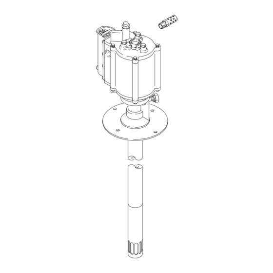
50:1 RATIO DOUBLE ACTING
Eaglet Grease Pumps
FOR LUBRICATING PRODUCTS ONLY
7500 psi (52 MPa, 517 bar) Maximum Fluid Working Pressure
150 psi (0.9 MPa, 10 bar) Maximum Air Input Pressure
Model 241351, Series A
35 lb (16 kg) Pail Size
Model 241352, Series A
120 lb (55 kg) Drum Size
Model 241353, Series A
400 lb (180 kg) Drum Size
U.S. Patent No. 5,147,188
R.O.C New Invention Patent No. 075540
Australian Patent No. 672050
Other Foreign Patents Pending
This manual contains important
warnings and information.
READ AND KEEP FOR REFERENCE.
GRACO INC. P.O. BOX 1441 MINNEAPOLIS, MN 55440–1441
ECOPYRIGHT 1999, GRACO INC.
Graco Inc. is registered to I.S. EN ISO 9001
308947
First choice when
quality counts.t
8757A
Rev. E
Advertisement
Table of Contents

Subscribe to Our Youtube Channel
Related Manuals for Graco Eagle A Series


Summary of Contents for Graco Eagle A Series
- Page 1 U.S. Patent No. 5,147,188 R.O.C New Invention Patent No. 075540 Australian Patent No. 672050 Other Foreign Patents Pending 8757A GRACO INC. P.O. BOX 1441 MINNEAPOLIS, MN 55440–1441 ECOPYRIGHT 1999, GRACO INC. Graco Inc. is registered to I.S. EN ISO 9001...
-
Page 2: Table Of Contents
D Read all instruction manuals, tags, and labels before operating the equipment. D Use the equipment only for its intended purpose. If you are not sure, call your Graco distributor. D Do not alter or modify this equipment. Use only genuine Graco parts and accessories. - Page 3 WARNING INJECTION HAZARD Fluid dispensed from the valve, leaks or ruptured components can inject fluid into your body and cause extremely serious injury, including the need for amputation. Fluid splashed in the eyes or on the skin can also cause serious injury. D Fluid injected into the skin might look like just a cut, but it is a serious injury.
- Page 4 WARNING FIRE AND EXPLOSION HAZARD Improper grounding, poor ventilation, open flames or sparks can cause a hazardous condition and re- sult in a fire or explosion and serious injury. D Ground the equipment and the object being dispensed to. Refer to Grounding on page 6. D If there is any static sparking or you feel an electric shock while using this equipment, stop dis- pensing immediately.
-
Page 5: Introduction
Introduction WARNING These pumps area designed to be used only in pumping non-corrosive and non-abrasive lubricants and greases. Any other use of the pump can cause unsafe operating conditions and component rup- ture, which can result in fluid injection or other serious injury, or fire or explosion. -
Page 6: Installation
Installation D Air hoses: Use only grounded air hoses. NOTE: Always use Genuine Graco Parts and Acces- sories, available from your Graco distributor. D Dispensing Valve: Obtain grounding through Grounding connection to a properly grounded fluid hose and pump. WARNING D Fluid supply container: Follow your local code. - Page 7 The Typical Installation shown in Fig. 3 is only a guide for selecting and installing system components and accessories. Contact your Graco distributor for assistance in designing a system to suit your particular needs. If you supply your own accessories, be sure they are adequately sized and pressure-rated to meet the system’s requirements.
- Page 8 Installation Mounting the Pump System Accessories 1. Select a convenient location for the equipment, to WARNING ensure easy operator access to the pump air controls, sufficient room to change supply contain- ers, and a secure mounting platform. Maximum Working Pressure 2.
- Page 9 Installation 4. Install a second bleed-type master air valve (G) WARNING upstream from all other accessories, to isolate the accessories for servicing. A bleed-type master air valve is required in your system to help reduce the risk of serious injury, 5.
-
Page 10: Operation
Operation Pressure Relief Procedure Flushing The pump is tested with lightweight oil, which is left in WARNING to protect the pump parts. If the fluid you are using may be contaminated by the oil, flush it out with a INJECTION HAZARD compatible solvent before using the pump. - Page 11 Operation Starting and Adjusting the Pump 5. Use the air regulator to control the pump speed WARNING and the fluid pressure. Always use the lowest air pressure necessary to get the desired results. To reduce the risk of serious injury whenever you Higher pressures cause premature nozzle and are instructed to relieve pressure, always follow the pump wear.
-
Page 12: Troubleshooting Chart
Troubleshooting Before servicing this equipment, always make sure to WARNING relieve the pressure. To reduce the risk of serious injury whenever you NOTE: Check all possible problems and solutions are instructed to relieve pressure, always follow the before disassembling the pump. Pressure Relief Procedure on page 10. - Page 13 Troubleshooting PROBLEM CAUSE SOLUTION Continuous air exhaust Worn or damaged motor piston o-ring (32). Inspect and replace. See page 21. from muffler. Air cup (7) not seating properly, or damaged. Inspect; reseat or replace. See page 24. Continuous air exhaust Worn or damaged carriage spool Inspect and replace.
-
Page 14: Service
Service Repair Kit 241355 D O-ring pick Repair Kit 241355 is available to service the displace- ment pump and air motor. Purchase the kit separately. D 9/32 in. or 7 mm socket wrench or nut driver For the best results, use all new parts in the kit. Parts included in the kit are denoted with an asterisk, for D 3/8 in. - Page 15 Displacement Pump Service Disconnecting the Air Motor WARNING To reduce the risk of serious injury whenever you are instructed to relieve pressure, always follow the Pressure Relief Procedure on page 10. 1. Relieve the pressure. Disconnect the fluid hoses and remove the pump from its mounting. 2.
- Page 16 Displacement Pump Service 8762A Fig. 6 Rotate the cylinder (101) 90 degrees so the hole is up. Run a punch through the hole in the cylinder to drive the pin (112) out. 8764A Fig. 7 308947...
- Page 17 Displacement Pump Service Reconnecting the Displacement Pump NOTE: Before connecting the displacement pump to 3. Use a pipe wrench on the lower part of the outlet the motor, check that a new copper gasket (39) is housing (18) to securely tighten the motor (1) to inserted in the outlet housing (18).
- Page 18 Displacement Pump Service Disassembly Reassembly 1. Disconnect the displacement pump from the air 1. If the priming piston (108) was removed from the motor (1), as explained on page 15. priming piston rod (107), reinstall it on the bottom threads of the rod (the end without a pin hole) and 2.
- Page 19 Displacement Pump Service Torque to 35 to 45 in-lb (4.0 to 5.1 N-m). Lubricate. Flat side must face retainer (106). Assemble pin (112*) flush or below surface. Large bevel must face piston (104). Torque to 15 to 20 ft-lb (20 to 27 N-m). Lubricate inside diameter.
- Page 20 Air Motor Service Throat Packing Service Disassembly Reassembly 1. Disconnect the air motor (1) from the displacement 1. Lubricate the u-cup packing (19*) and install it in pump, as explained on page 15. the bottom cylinder cap (4), with the lips facing up toward the air motor (1).
- Page 21 Air Motor Service Cylinder and Piston Service Disassembly Reassembly 1. Disconnect the air motor (1) from the displacement 1. Grease the large o-ring (22*) and the two small pump, as explained on page 15. o-rings (34*) and install them on the top cylinder cap (5).
- Page 22 Air Motor Service Actuator Valve Service Disassembly Reassembly 1. Remove the actuator valve plug (11) from the top 1. If the o-ring (24*) was removed, it must be cap (5). Inspect the sealing gasket (15*) and installed from the inside of the top cap (5). Lubri- spring (16*) in place on the plug.
- Page 23 Air Motor Service Lubricate with grease. Torque to 14 to 17 in-lb (1.6 to 1.9 N-m). Torque to 60 to 80 in-lb (6.8 to 9.0 N-m). Grease inner wall. Long end of pin must point toward inside of motor. 17 (REF) 8760B Fig.
- Page 24 Air Motor Service Director Valve Service Disassembly Reassembly NOTE: Pump Repair Kit 241355 is available. Also, 1. Install the valve gasket (13) and plate (8) on the director valve assembly 241357 is available by itself. cylinder (2). Be sure the surface of the plate facing For the best results, use all the new parts in the kit.
- Page 25 Air Motor Service lips down lips up Torque to 4 to 6 in-lb (0.5 to 0.7 N-m). Lubricate with grease. Grease inside diameter. Clips (3f) must be installed from inside of housing (3a). Torque to 14 to 17 in-lb (1.6 to 1.9 N-m). Lips point toward center of spool.
-
Page 26: Parts Drawing
Parts Drawing *112 *105 *111 17 (REF) 107 (REF) 102 (REF) *103 112* 8756B 308947... -
Page 27: Parts List
Parts List Model 241351 Pump, Series A 35 lb (16 kg) Pail Size Model 241352 Pump, Series A 120 lb (55 kg) Drum Size Model 241353 Pump, Series A 400 lb (180 kg) Drum Size NO. PART NO. DESCRIPTION NO. PART NO. DESCRIPTION 241267 AIR MOTOR;... -
Page 28: Technical Data
Technical Data Maximum fluid working pressure ......7500 psi (52 MPa, 517 bar) Maximum air inlet pressure . -
Page 29: Dimensions And Mounting Hole Layout
Dimensions Model No. Weight 241351 27.369 in. 17.489 in. 9.88 in. 7.102 in. 11 lb (695 mm) (444 mm) (251 mm) (180 mm) (5.0 kg) 241352 36.619 in. 26.739 in. 9.88 in. 7.102 in. 14 lb (930 mm) (679 mm) (251 mm) (180 mm) (6.4 kg) -
Page 30: Performance Charts
Performance Charts 50:1 Eagle Grease Pumps Fluid Outlet Pressure Test Fluid: No. 2 grease (specific gravity: 0.92) Cycles Per Minute* 8000 (56, 560) 7000 (49, 490) 6000 (42, 420) 5000 (35, 350) 4000 (28, 280) 3000 (21, 210) 2000 (14, 140) 1000 (7, 70) (0.18) - Page 31 Performance Charts 50:1 Eagle Grease Pumps Air Consumption Test Fluid: No. 2 grease (specific gravity: 0.92) Cycles Per Minute* È È È È È È È È È È È È È È È È È È È È È È È È È È È È (0.896) Fluid Pressure Curves È...
-
Page 32: Graco Standard Warranty
Graco distributor to the original purchaser for use. With the exception of any special, extended, or limited warranty published by Graco, Graco will, for a period of twelve months from the date of sale, repair or replace any part of the equipment determined by Graco to be defective.
Need help?
Do you have a question about the Eagle A Series and is the answer not in the manual?
Questions and answers