Table of Contents
Advertisement
Quick Links
Instructions
EcoQuip 2
Vapor Abrasive Blast System
Vapor abrasive blast system for coating removal and surface preparation.
For professional use only.
175 psi (12.06 bar, 1.2 MPa) Maximum Air Working Pressure
See page 3 for models and approval information.
Important Safety Instructions
Read all warnings and instructions in this
manual before using this equipment.
Save these instructions.
™
EQm
3A3489T
EN
Advertisement
Table of Contents

Related Manuals for Graco EcoQuip 2 EQm


Summary of Contents for Graco EcoQuip 2 EQm
- Page 1 Instructions ™ EcoQuip 2 3A3489T Vapor Abrasive Blast System Vapor abrasive blast system for coating removal and surface preparation. For professional use only. 175 psi (12.06 bar, 1.2 MPa) Maximum Air Working Pressure See page 3 for models and approval information. Important Safety Instructions Read all warnings and instructions in this manual before using this equipment.
-
Page 2: Table Of Contents
California Proposition 65 ....51 Graco Standard Warranty ....52... -
Page 3: Related Manuals
Related Manuals Related Manuals Manual in English Description EcoQuip 2 EQs,EQc, and EQ Trailer 3A7467 Unit Vapor Abrasive Blast System ™ 313840 DataTrak 333397 Pump 335035 Air Inlet Kit 309474 Low Pressure Fluid Regulators 3A3838 Nozzle Pressure Verification Kit 3A3839 Nozzle Extension Handle Kit 3A3970 Water Dose Kit... -
Page 4: Series Change
Series Change Series Change The EcoQuip pressure pot has been updated with a new pop-up assembly and the addition of a quick drain ball valve assembly to simplify the process for filling and draining the pot. System Series D (262950, 262951) New Pop-up Assembly... -
Page 5: Warnings
Warnings Warnings The following warnings are for the setup, use, grounding, maintenance, and repair of this equipment. The exclamation point symbol alerts you to a general warning and the hazard symbols refer to procedure-specific risks. When these symbols appear in the body of this manual or on warning labels, refer back to these Warnings. Product-specific hazard symbols and warnings not covered in this section may appear throughout the body of this manual where applicable. - Page 6 Warnings WARNING EQUIPMENT MISUSE HAZARD Misuse can cause death or serious injury. • Do not operate the unit when fatigued or under the influence of drugs or alcohol. • Do not exceed the maximum working pressure or temperature rating of the lowest rated system component.
- Page 7 Warnings WARNING MOVING PARTS HAZARD Moving parts can pinch, cut, or amputate fingers and other body parts. • Keep clear of moving parts. • Do not operate equipment with protective guards or covers removed. • Pressurized equipment can start without warning. Before checking, moving, or servicing equipment, follow the Pressure Relief Procedure and disconnect all power sources.
-
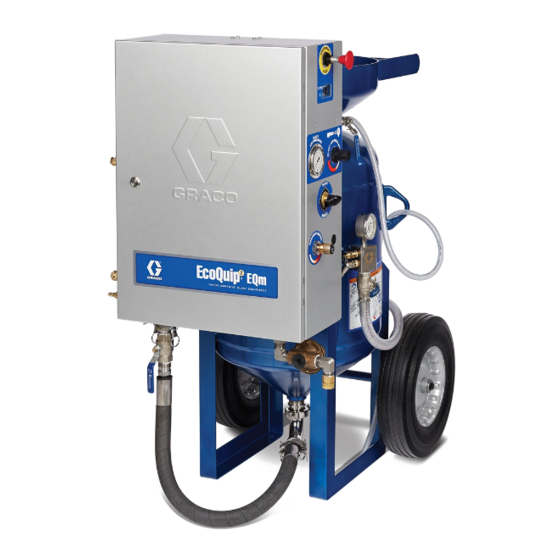
Page 8: Component Identification
Component Identification Component Identification 3A3489T... -
Page 9: Mediatrak Controls
Component Identification MediaTrak Controls Key: Blast Control Switch Blast Nozzle Blast Hose Pot Seal Plunger Pot Dump Valve Pressure Relief Valve Pot Pressure Gauge Abrasive Ball Valve Control Box Emergency Stop Blast Air Regulator Water Dose Valve Key: Abrasive Metering Valve Power Key Water Pump Inlet Filter Cycle/Rate... -
Page 10: Installation
Lift the system using the lift eyes shown on the (237686). following illustration. Air and fluid hoses: Use only genuine Graco conductive blast hoses with a maximum of 150 ft (45 m) combined blast hose length to ensure grounding continuity. Check the electrical resistance of the blast hoses. -
Page 11: Blast Hose Selection
Installation Blast Hose Selection Pinch Hose Inspection Make sure to use the correct type of blast control. An Inspect the pinch hose at the start of each job, or electric or pneumatic blast control switch can be used monthly, looking for “bubbles” in the outer casing. If with hose lengths less than 150 ft (45 m). -
Page 12: Connect The Blast Hose And Air Hose
Installation Connect the Blast Hose and Air 3. Connect an appropriately sized air supply hose to the air inlet and install coupler pins. See Technical Hose Specifications, page 51. 1. ATEX models only: Connect the grounding cable to th external ground stud on the enclosure, then connect the clamp to a true earth ground. -
Page 13: Connect The Water Supply
Installation Connect the Water Supply Failure to fully secure the blast hoses may cause hoses to detach during operation. To help prevent serious injury from flying debris, always install the 1. Connect to a water supply hose with a minimum ID blast hose restraints and coupler pins. -
Page 14: Setup
Setup Setup Fill Pot with Abrasive Media 5. Open the pot dump valve (F) and quick drain valve (ZH). 1. Verify that the pot seal plunger (E) is in the DOWN position. If the plunger is in the UP position, perform the Pressure Relief Procedure on page 17. - Page 15 Setup 8. Add abrasive media to the pot. 9. With a garden hose or the rinse valve (U), wash the abrasive into the pot and clear any abrasive from NOTE: The media level should be a few inches below the pot seal plunger (E) and pot seal gasket. the pot seal plunger (E).
-
Page 16: Pressurize The Pot
Setup Pressurize the Pot NOTE: The water pump will not work unless the Emergency Stop is disengaged. 5. Turn the selector valve (T) to BLAST To avoid injury to the operator, always pressurize the pot before opening the abrasive ball valve (J) or engaging the blast control switch (A). -
Page 17: Operation
Operation Operation 4. Engage the blast control switch (A) to relieve pressure in the system. 5. Verify that the supply pressure gauge (Z) reads 0 This equipment may introduce dust and debris into psi. Then disconnect the air inlet hose from the the air. -
Page 18: Adjust Blast Pressure
Operation Adjust Blast Pressure 4. Adjust the blast air regulator (M) until the desired pressure appears on the blast pressure gauge (H). NOTE: Do not increase directly to blast pressure. Always set below the desired pressure, then increase to the actual setpoint. To avoid injury due to a spray from wet media from the pot, always Pressurize the Pot, page 16, before opening the abrasive ball valves (J) and engaging the... -
Page 19: Adjust Abrasive Media
Operation Adjust Abrasive Media NOTE: You may have to wait 1-2 minutes for the abrasive material to reach the nozzle. 1. Perform the Adjust Blast Pressure procedure on NOTE: Use a piece of test material similar to what you page 18. will be blasting. -
Page 20: Refill The Pot With Media
Operation Refill the Pot with Media Optimize the Abrasive Metering Value As abrasive media leaves the pot during blasting, follow the Fill Pot with Abrasive Media procedure, page 14. To optimize performance, use the High Production or NOTE: If the pot loses pressure, follow the Pressurize Media Efficient lines on the charts. -
Page 21: General Application Guides
Operation General Application Guides General Application Guide (Steel) Steel Typical Setting High Production Media Efficient Blast Pressure (psi) General Application Guide (Concrete/Masonry) Concrete/Masonry Typical Setting High Production Media Efficient Blast Pressure (psi) General Application Guide (Fiberglass) Fiberglass Typical Setting High Production Media Efficient Blast Pressure (psi) ti28396b... -
Page 22: Nozzle Selection Guide
Operation Nozzle Selection Guide Use the Blast Pressure vs. Air Flow Guide to determine which nozzle to use to achieve the desired blast pressure based on compressor output. Blast Pressure vs. Air Flow Guide #6HP CFM #7 CFM #7HP CFM #8 CFM #8HP CFM #10 CFM... -
Page 23: Use The Wash Feature
Operation Use the Wash Feature 2. Turn the selector valve (T) to WASH. The wash feature uses water (without abrasive) to rinse areas that have been blasted with abrasive. It is also a convenient feature for flushing abrasive from the blast hose. -
Page 24: Standby
Operation Standby Shutdown 1. Close the abrasive ball valve (J). NOTICE To prevent material from packing out and damaging blast hoses, ensure that the abrasive ball valves are fully closed before shutting off your air compressor. 1. When you have finished blasting, use the wash feature to flush all of the abrasive from the blast hose. -
Page 25: Drain The Pot
Operation Drain the Pot 5. Place a bucket under the abrasive hose. Slowly open and close the abrasive ball valve (J) to flush abrasive material from the pot. Repeat several times. Once no abrasive material flows from the hose, close the abrasive ball valve (J). NOTE: Before draining the pot, verify that all steps in Pressurize the Pot, page 16, have been followed. -
Page 26: Winterize The Equipment
Operation Winterize the Equipment 4. Move the selector valve (T) into the other two positions (BLAST and OFF). Confirm that the internal water tubing fills with windshield wash before turning the selector valve to the next position. NOTE: All water tubing should be filled with windshield wash for full protection. -
Page 27: Troubleshooting
Troubleshooting Troubleshooting Problem Cause Solution Unable to fill or The emergency stop Disengage the emergency stop (L). pressurize the pot with (L) is engaged. water. The air supply is Make sure the air compressor is capable of suppling the minimum inadequate. - Page 28 Troubleshooting Problem Cause Solution The blast hose recoils The abrasive ball valve See Shutdown, page 24, step 2. heavily when the blast was left open during control switch (A) is shut down. engaged. Large slugs The abrasive ball valve With the pot pressurized and the abrasive ball valve closed, of abrasive and water is worn.
- Page 29 Troubleshooting Problem Cause Solution No blast air flow when The emergency stop Disengage the emergency stop (L). the blast control (L) is engaged. switch (A) is engaged. The air supply is Make sure the air compressor is capable of supplying the minimum The water pump does inadequate.
- Page 30 Troubleshooting Problem Cause Solution While in BLAST The abrasive ball valve See Setup, page 14. mode, with the blast is closed. control switch (A) The abrasive metering See Setup, page 14. engaged, air is flowing valve is not properly from the nozzle but set.
- Page 31 Troubleshooting Problem Cause Solution The blast control The air supply is Make sure the air compressor is capable of supplying the minimum switch (A) is not inadequate. air flow requirements for your system. See , page 50. Makes sure engaged, but blasting the air inlet pressure gauge reads 100-175 psi (6,8-12 bar, occurs.
- Page 32 Troubleshooting Problem Cause Solution The blast spray The air supply is Make sure the air compressor is capable of supplying the pattern is sputtering or inadequate. minimum air flow requirement for your system. See , page 50. irregular. Make sure the air inlet pressure gauge reads 100-175 psi (6.8-12 bar, 0.68-1.2 MPa).
-
Page 33: Repair
To reduce the risk of fire and explosion, the battery must be replaced in a non-hazardous location. Use only an approved replacement battery (see table). Use of an unapproved battery will void Graco's warranty. Replace Battery 1. Unscrew cable from the back of the reed switch assembly. -
Page 34: Replace The Datatrak Fuse
To reduce the risk of fire and explosion, the fuse must be replaced in a non-hazardous location. Fuse Use only an approved replacement fuse (see table). Use of an unapproved fuse will void Graco's warranty. Replace Fuse 1. Remove the screw, metal strap, and plastic holder. -
Page 35: Replace The Pinch Hose
Repair Replace the Pinch Hose Install the Pinch Hose 1. Reinstall the check valve, ensuring proper Remove the Pinch Hose orientation. Assemble the valve with the plunger facing the bent manifold. 2. Place both hose clamps (C1, C2) on the pinch hose (PH). -
Page 36: Parts
Parts Parts EQm Parts Apply thread sealant to all non-swivel pipe threads. Apply anti-seize to enclosure mounting studs. Apply anti-seize to threads. Torque to 25-30 ft-lb (34-40.6 N•m). Torque to 15 +/- 2 ft-lb (20.3 +/- 2.7 N•m) 3A3489T... - Page 37 Parts The hand-way gasket must be installed centered and flat on Apply thread sealant to all non-swivel pipe threads. the hand-way cover. Apply anti-seize to threads. Apply anaerobic sealant to threads. Torque to 60 +/- 5 ft-lb (81.3 +/- 6.7 N•m) with pot pressurized.
- Page 38 Parts EQm Parts List Ref. Part Description Qty. Ref. Part Description Qty. 17D787 PIN, safety item, hose, hair c ------- PRESSURE POT, blast media, 3.5 (6 pack) cu ft 206994 FLUID, TSL 8 oz. bottle 17L310 SEAL, o-ring EQ1829 FITTING, ground boss, spud, 1-1/2 17L046 VALVE, ball, 1 npt sst -------...
-
Page 39: Enclosure Box Parts
Parts Enclosure Box Parts Torque fitting with pump outlet fitting to 35–40 ft-lb (47.4–54.2 N•m). Apply thread sealant to needle valve knob screw when reassembling. Align knob with ‘D’ facing up when in closed position. Apply thread sealant to selector valve handle set screw when reassembling. 3A3489T... - Page 40 Parts Enclosure Box Parts List Ref. Part Description Qty. Ref. Part Description Qty. 17H280 NUT, m20, needle valve 25D023 PANEL, enclosure, EQm EQ1115 BULKHEAD, connector, union, 3/8 3 17L807 LABEL, notice ------- BRACKET, pump 112268 SWIVEL, union 25A531 PUMP, water, sst, 3:1 17L324 REGULATOR, pressure, water, 128483 GROMMET, pump, EQ2 185 psi (includes 75)
- Page 41 Parts Enclosure Box Parts (continued) Apply thread sealant to emergency stop valve stem when reassembling the red knob. 3A3489T...
- Page 42 Parts Enclosure Box Parts List (continued) Ref. Part Description Qty. Ref. Part Description Qty. 127917 NUT, flange, serrated, 1/4-20, ss ------- BRACKET, EcoQuip, DataTrak 17C001 GASKET, EcoQuip, DataTrak 17K057 ENCLOSURE, DataTrak, EcoQuip 128502 SCREW, pan, type F, #10-24, 3/8, 121022 FITTING, elbow, male 1/4 npt 17L319 GAUGE, flange mount, 2.5 in., 75†...
-
Page 43: Enclosure Parts (Eqm Only)
Parts Enclosure Parts (EQm only) Apply anti-seize to threads on clamp (62). Align Assemble valve (17) with plunger facing the bent the nuts pointing towards the front of the manifold (16). enclosure. Torque nuts to 85 +/- 5 in-lb (9.6 +/- 0.5 N•m). Apply anti-seize to threads on clamp (17g and 60). - Page 44 Parts Enclosure Parts List (EQm only) Ref. Part Description Qty. Ref. Part Description Qty. 17G578 MANIFOLD, blast circuit, 1.0, 17K052 VALVE, pinch bottom ------- SEAL, wiper 680454 GASKET, sanitary fitting ------- SEAL, o-ring 19A742 MANIFOLD, slurry, barb/cam-lock 121022 FITTING, elbow, male, 1/4 npt 128638 FITTING, ptc, straight, 3/8 17G574 NUT, bulkhead, 2-1/4, sst 128637 FITTING, ptc, straight, 1/4...
-
Page 45: Blast Hoses
Parts Blast Hoses For Use with Mini Electric Plugs Electric, 50 ft Ref. Part Description Qty. 26A024 (1.25 in.), 26A074 (1.0 in.) 17L274 HOLDER, 1.25 in. 17L276 HOLDER, 1.0 in. 17L273 COUPLER, 1.25 in. 17L275 COUPLER, 1.0 in. 17D788 HANDLE, blast control switch, pneumatic 17L331 HANDLE, switch, electric 24X746 HOSE, pneumatic, control, blast... - Page 46 Parts For Use with Standard Electric Plugs Electric, 50 ft Ref. Part Description Qty. 28A024 (1.25 in.), 28A074 (1.0 in.) 17L274 HOLDER, 1.25 in. 17L276 HOLDER, 1.0 in. 17L273 COUPLER, 1.25 in. 17L275 COUPLER, 1.0 in. 17D791 HANDLE, switch, electric 17F506 CABLE, blast control 17L472 HOSE, blast, 1.25 in.
-
Page 47: Vapor Abrasive Blast Systems And Accessories
Vapor Abrasive Blast Systems and Accessories Vapor Abrasive Blast Systems and Accessories 50 ft (15 m) Blast Hoses with Control Hose/Cable Electric Plug ATEX Part Blast Control Type Coupler 1 Coupler 2 Approved 26A077 1.0 in. Pneumatic 26A076 1.0 in. Electric Mini 2-prong coupler, brass... -
Page 48: Other Accessories
Vapor Abrasive Blast Systems and Accessories Other Accessories Part Description 17L119 KIT, nozzle gasket (pack of 5) EQ5166 KIT, nozzle extension, 24 in. (0.6 m) 26A029 KIT, nozzle extension, 24 in. (0.6 m), with handles 17J958 KIT, nozzle pressure verification tool 17K025 KIT, pot strainer 16A002... -
Page 49: Tubing Schematic
Tubing Schematic Tubing Schematic Ref. Part Color, Tube Size Cut Length inches (mm) EQ1273 Natural, 3/8 in. OD 12.25 (311) EQ1273 Natural, 3/8 in. OD 15.5 (394) EQ1273 Natural, 3/8 in. OD 19 (483) EQ1273 Natural, 3/8 in. OD 5.25 (133) EQ1273 Natural, 3/8 in. -
Page 50: Dimensions
Dimensions Dimensions EQm Models 3A3489T... -
Page 51: Technical Specifications
Technical Specifications Technical Specifications EcoQuip 2 EQm Metric Maximum Inlet Air Pressure 175 psi 10.3 bar, 1.03 MPa Maximum Inlet Water Pressure 100 psi 6.9 bar, 0.69 MPa Operating Temperature 35°–110° F 1.6°–43.3° C Recommended Compressor Size+ 185–600 CFM 5.3–17 m3/min 31.75 mm ID... -
Page 52: Graco Standard Warranty
With the exception of any special, extended, or limited warranty published by Graco, Graco will, for a period of twelve months from the date of sale, repair or replace any part of the equipment determined by Graco to be defective.
Need help?
Do you have a question about the EcoQuip 2 EQm and is the answer not in the manual?
Questions and answers