Table of Contents
Advertisement
Quick Links
PEAK
Scientific Instruments Ltd
Instructions for use Manual
ZA015 Issue 3
Directions For Use
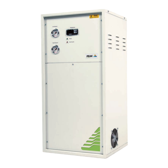
Zero Air Gas Generator
ZA015 - ZA180
Peak Scientific Instruments Ltd
Fountain Crescent
Inchinnan Business Park
Inchinnan
Renfrewshire
PA4 9RE
T.(Europe) +44 (0) 141 812 8100
T.(USA) +1 866 647 1649 (sales)
T.(USA) +1 866 732 5427 (tech support)
F.(Europe) +44 (0) 141 812 8200
info@peakscientific.com
sales@peakscientific.com
support@peakscientific.com
www.peakscientific.com
Zero Air Gas Generator
th
30
March 2005
1
Advertisement
Table of Contents

Subscribe to Our Youtube Channel
Related Manuals for Peak Scientific ZA015


Summary of Contents for Peak Scientific ZA015
- Page 1 Zero Air Gas Generator PEAK Scientific Instruments Ltd Instructions for use Manual March 2005 Directions For Use Zero Air Gas Generator ZA015 - ZA180 Peak Scientific Instruments Ltd Fountain Crescent Inchinnan Business Park Inchinnan Renfrewshire PA4 9RE T.(Europe) +44 (0) 141 812 8100 T.(USA) +1 866 647 1649 (sales)
-
Page 2: Document History
Zero Air Gas Generator PEAK Scientific Instruments Ltd Instructions for use Manual March 2005 Document Change History Issue No Changed Initials Date Document Created 01/09/98 USA Technical support number updated 16/11/04 New style front added 30/03/05 ZA015 Issue 3... -
Page 3: Table Of Contents
Scientific Instruments Ltd Instructions for use Manual March 2005 Contents Page No Document History Warranty Statement Introduction Unpacking & Installation Electrical Connection Air Connection Principle of Operation Commissioning Routine Maintenance Troubleshooting Technical Specifications System Diagrams Maintenance Log Notes ZA015 Issue 3... - Page 4 March 2005 Safety First It is important that you thoroughly read and understand this manual before operating or servicing this Peak Scientific Instruments Gas Generator. PLEASE NOTE THE FOLLOWING CAUTIONS AND WARNINGS FOR YOUR OWN SAFETY. ! Caution – Only authorized persons should operate or service this equipment.
-
Page 5: Warranty Statement
These instructions must be read thoroughly and understood before installation and operation of your Peak Gas Generator. Use of the Generator in a manner not specified by Peak Scientific Inst. MAY impair the SAFETY provided by the equipment. When handling, operating or carrying out any maintenance, personnel must employ safe engineering practices and observe all relevant local health and safety requirements and regulations. -
Page 6: Introduction
Instructions for use Manual March 2005 Introduction The Peak Scientific Instruments range of Zero Air Gas Generators is designed to produce a constant flow of Zero Grade Air with a Hydrocarbon content (as Methane) of less than 0.1 ppm. Unpacking and Installation Although Peak Scientific take every precaution with safe transit and packaging, it is advisable to fully inspect the unit for any sign of transit damage. -
Page 7: Air Connection
The user should therefore ensure that the application only receives a maximum flow not exceeding the rating for the generator. Demand in excess of the rated capacity of will result in higher levels of hydrocarbons in the delivered gas. ZA015 Issue 3... -
Page 8: Principle Of Operation
Celsius. The free Carbon and Hydrogen atoms then combine with Oxygen in the air to form Carbon Dioxide and Water. After the catalytic chamber the air passes through a simple cooling coil to reduce its temperature to a safe level. In the ZA180 this is assisted by a cooling fan. ZA015 Issue 3... -
Page 9: Commissioning
However as with all scientific and technical equipment it should be regularly inspected by a competent person and the following points noted. 1. Inlet Filter. Condensed moisture should be periodically drained from the filter. 2. Temperature Control. Check that the red LED cycles On & Off. ZA015 Issue 3... -
Page 10: Troubleshooting
Reference to the following Fault Finder Chart will identify the source of the problem. Cat Chamber Hot/ Check High CH4 Cold Flow Rate Cold Control Board LED Off Open Circuit Thermocouple Wiring Voltage At Heater Voltage At Replace Replace Board Output Control Board Thermocouple Replace Heater Check Wiring ZA015 Issue 3... -
Page 11: Technical Specifications
Heater Element 04-1059 04-1059 04-1059 04-1059 Thermocouple 04-1051 04-1051 04-1051 04-1051 Temperature Controller 04-1170 04-1170 04-1170 04-1170 Cooling Fan (240V) 04-1021 04-1021 04-1021 04-1021 Cooling Fan (110V) 04-1022 04-1022 04-1022 04-1022 Transformer (230V Only) 04-4356 04-4356 04-4356 04-4356 ZA015 Issue 3... -
Page 12: System Diagrams
March 2005 System Diagrams Heater Rod Thermocouple Cooling Inlet Filter / Coil Regulator Outlet Chamber ZAxxx Pneumatic Diagram Temperature Switch Controller (400 Deg C) Fuse Transformer (230V Only) Fan Motor (ZA180 only) Heater Thermocouple ZAxxx Electrical Diagram ZA015 Issue 3... -
Page 13: Maintenance Log
Zero Air Gas Generator PEAK Scientific Instruments Ltd Instructions for use Manual March 2005 Maintenance Log Model- Serial number Work Done Remarks Date Name ZA015 Issue 3... -
Page 14: Notes
Zero Air Gas Generator PEAK Scientific Instruments Ltd Instructions for use Manual March 2005 Notes ZA015 Issue 3...
Need help?
Do you have a question about the ZA015 and is the answer not in the manual?
Questions and answers