Table of Contents
Advertisement
Quick Links
Advertisement
Table of Contents

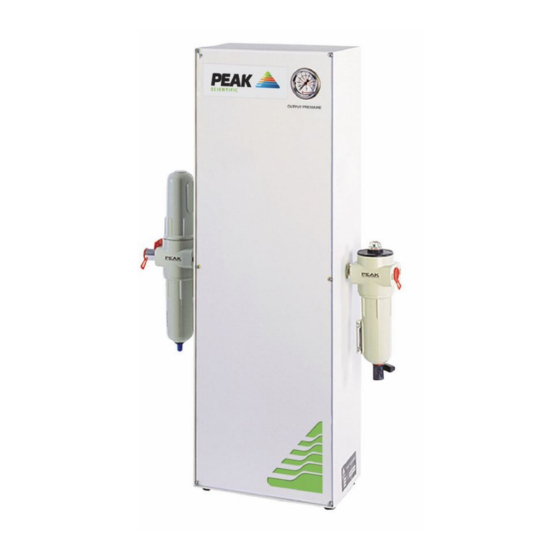
Summary of Contents for Peak Scientific Infinity 9000
- Page 1 Infinity 9000 User Manual 2014 © Peak Scientific - Rev. 2 - 28/05/14...
-
Page 2: Table Of Contents
Technical Specifications Environment Inlet Conditions Outlet Gas General Introduction Unpacking and Installation General Dimensions Air Connection Fittings Kit Commissioning Pressure & Flow Settings Maintenance Schedule Service Schedule Safely Isolated Condition Page 2 2014 © Peak Scientific - Rev. 2 - 28/05/14... -
Page 3: Change History
Please review each of the following sections carefully. Thank you for selecting Peak Scientific to meet your Gas Generation needs, should you require any further assistance or support please do not hesitate to contact Peak Scientific or the Peak Partner from which you purchased your Generator. -
Page 4: Warranties And Liabilities
(other than pursuant to clause 6 above) that may be suffered by the Customer or any third party. Page 4 2014 © Peak Scientific - Rev. 2 - 28/05/14... -
Page 5: Safety Notices
Safety Notice to Users These instructions must be read thoroughly and understood before installation and operation of your Peak Scientific Infinity 9000. Use of the Generator in a manner not specified by Peak Scientific MAY impair the SAFETY provided by the equipment. -
Page 6: Technical Specifications
Maximum Gas output flow (zero grade air) 34 l/min (ATP) Start-up time for purity 60 minutes Particles 0.01um General Dimensions (cm/ins) WxDxH 47x16x76 / 19x7x30 Shipping Weight (Kg/lbs) 21 / 46 Page 6 2014 © Peak Scientific - Rev. 2 - 28/05/14... -
Page 7: Introduction
Check ‘SHOCKWATCH’ label for signs of rough handling prior to un-packing – Any damage should be reported immediately to the carrier and Peak Scientific or the Peak Partner from where the unit was purchased. -
Page 8: General Dimensions
In addition to being floor or bench free standing, the generator may be fixed to a wall in the upright position shown below. The diagram shows the clearances and mounting hole centres required. *Dimensions in mm. Page 8 2014 © Peak Scientific - Rev. 2 - 28/05/14... -
Page 9: Air Connection
A minimum inlet pressure of 100 psig (6.7 barg) is required. Any doubts as to the suitability of your compressed air supply should be referred to Peak Scientific or any of their authorised partners. The generator has a Breathing Air Filter with ¼” BSPT connection to the left side of the unit. -
Page 10: Commissioning
34l/min @ 100psig The above settings should allow the generator to be operated with all standard configurations of instruments. Should the above settings not provide sufficient flow or pressure for your application please contact Peak Scientific for assistance. Page 10... -
Page 11: Maintenance Schedule
Ensure the output pressure gauge read zero. (If gauge does not fall to zero, loosen the outlet fitting slightly to allow trapped gas to escape). Disconnect from the application. Page 11 2014 © Peak Scientific - Rev. 2 - 28/05/14... - Page 12 3. Remove the filter element by pulling it away from the filter assembly. 4. Fit the replacement elements. 5. Re-fit the filter bowls. 00-0046 00-0045 Page 12 2014 © Peak Scientific - Rev. 2 - 28/05/14...
- Page 13 For easier access, the filter assembly can be removed from the cabinet by removing the 4 of nyloc nuts and disconnecting the tubing. 3. Remove and replace the filter element and re-assemble. 00-0041 Page 13 2014 © Peak Scientific - Rev. 2 - 28/05/14...
- Page 14 São Paulo SP Brasil 107-0061 Singapore, 118223 Tel: +886 2 8226 2383 Tel: +1 866 647 1649 Tel: +81 3-6864-0468 Tel: +65-6777 1966 Fax: +886 2 8226 9499 Fax: +65-6777 1978 2014 © Peak Scientific - Rev. 2 - 28/05/14...


Need help?
Do you have a question about the Infinity 9000 and is the answer not in the manual?
Questions and answers