Festo MPS Station Manual
Separating station
Hide thumbs
Also See for MPS Station:
- Manual (116 pages) ,
- Circuit diagrams (11 pages) ,
- Manual (104 pages)

Related Manuals for Festo MPS Station


Summary of Contents for Festo MPS Station
- Page 1 Station Trennen Handbuch Separating station Manual CD-ROM included 696682 DE/EN 04/06 R2.2...
- Page 2 Ausbildungsunternehmens und/oder sonstiger Dritter aus, die bei Gebrauch/Einsatz der Anlage außerhalb einer reinen Ausbildungssituation auftreten; es sei denn Festo Didactic hat solche Schäden vorsätzlich oder grob fahrlässig verursacht. This station has been developed and produced solely for vocational and further training purposes in the field of automation and communication.
-
Page 3: Table Of Contents
6.3.1 Näherungsschalter, induktiv (Modul Weiche) _______________________ 31 6.3.2 Reflex-Lichttaster (Modul Verzweigen, Werkstücknachweis) ___________ 32 6.3.3 Reflex-Lichttaster (Modul Unterscheiden, Werkstückidentifikation) _____ 33 6.3.4 Einweg-Lichtschranke (Modul Verzweigen, Werkstücknachweis) _______ 34 Sichtprüfung _________________________________________________ 35 © Festo Didactic GmbH & Co. KG • 696682... - Page 4 Kombination von Stationen______________________________________ 52 6.10.1 Vernetzung___________________________________________________ 52 6.10.2 Hardwareanpassungen _________________________________________ 52 Wartung _____________________________________________________ 53 Inhalt der CD-ROM ___________________________________________________ 55 Schaltpläne __________________________________________________ 55 Programmierung ______________________________________________ 55 Bedienungsanleitungen ________________________________________ 55 Datenblätter__________________________________________________ 56 Aktualisierungen ____________________________________________________ 57 © Festo Didactic GmbH & Co. KG • 696682...
- Page 5 Diffuse sensor (Branching module, detection of workpieces)___________ 86 6.3.3 Diffuse sensor (Differentiation module, identification of workpieces) ____ 87 6.3.4 Through-beam sensor (Branching module, detection of workpieces) ____ 88 Visual check __________________________________________________ 89 © Festo Didactic GmbH & Co. KG • 696682...
- Page 6 6.10.1 Networking__________________________________________________ 106 6.10.2 Hardware modifications _______________________________________ 106 Maintenance ________________________________________________ 107 Content of the CD-ROM ______________________________________________ 109 Circuit diagrams______________________________________________ 109 Programming ________________________________________________ 109 Operating instructions_________________________________________ 109 Data sheets _________________________________________________ 110 Updates _________________________________________________________ 111 © Festo Didactic GmbH & Co. KG • 696682...
-
Page 7: Einleitung
Einleitung Das Lernsystem Automatisierung von Festo Didactic orientiert sich an unterschiedlichen Bildungsvoraussetzungen und beruflichen Anforderungen. Die ® Anlagen und Stationen des Modularen Produktions-Systems (MPS ) ermöglichen eine an der betrieblichen Realität ausgerichtete Aus- und Weiterbildung. Die Hardware setzt sich aus didaktisch aufbereiteten Industriekomponenten zusammen. -
Page 8: Lerninhalte
– • Ersetzen der pneumatischen Komponenten durch elektrische Komponenten • SPS Programmierung Programmieren von Zählern – Programmieren eines Zwischenspeichers für Werkstückparameter – Programmieren eines Betriebsartenteils – Programmieren des RICHTEN Ablaufs – © Festo Didactic GmbH & Co. KG • 696682... -
Page 9: Wichtige Hinweise
Alle Personen, die mit Arbeiten am MPS beauftragt sind, verpflichten sich, vor Verpflichtung der Arbeitsbeginn: Auszubildenden • das Sicherheitskapitel und die Warnhinweise in diesem Handbuch zu lesen, • die grundlegenden Vorschriften über Arbeitssicherheit und Unfallverhütung zu beachten. © Festo Didactic GmbH & Co. KG • 696682... -
Page 10: Gefahren Im Umgang Mit Dem Modularen Produktions-System
Maschine oder an anderen Sachwerten entstehen. ® Das MPS ist nur zu benutzen: • für die bestimmungsgemäße Verwendung und • in sicherheitstechnisch einwandfreiem Zustand. Störungen, die die Sicherheit beeinträchtigen können, sind umgehend zu beseitigen! © Festo Didactic GmbH & Co. KG • 696682... -
Page 11: Gewährleistung Und Haftung
Ausbildungsunternehmens und/oder sonstiger Dritter aus, die bei Gebrauch/Einsatz der Anlage außerhalb einer reinen Ausbildungssituation auftreten; es sei denn Festo Didactic hat solche Schäden vorsätzlich oder grob fahrlässig verursacht. Diese Station ist ausschließlich für die Aus- und Weiterbildung im Bereich Bestimmungsgemäße... - Page 12 1. Einleitung © Festo Didactic GmbH & Co. KG • 696682...
-
Page 13: Sicherheitshinweise
• Seien Sie beim Einschalten der Druckluft besonders vorsichtig. Zylinder können selbsttätig aus- oder einfahren. Mechanik • Montieren Sie alle Elemente fest auf die Platte. • Greifen Sie nur bei Stillstand in die Station. © Festo Didactic GmbH & Co. KG • 696682... - Page 14 2. Sicherheitshinweise © Festo Didactic GmbH & Co. KG • 696682...
-
Page 15: Technische Daten
(PR) Bearbeiten (BE) Handhaben (HA) Puffern (PU) Pick&Place (PP) FluidicMuscle Presse (FP) Trennen (TR) Lagern (LA) Roboter Montieren* (MO/HS) * Montieren mit Stanzen / ** Sortieren DP / *** Verteilen AS-Interface © Festo Didactic GmbH & Co. KG • 696682... - Page 16 3. Technische Daten © Festo Didactic GmbH & Co. KG • 696682...
-
Page 17: Transport/Auspacken/Lieferumfang
Die Transportbox darf ausschließlich mit geeigneten Hubwagen oder Gabelstaplern transportiert werden. Die Transportbox muss gegen Umfallen und Herunterfallen gesichert sein. Transportschäden sind unverzüglich dem Spediteur und Festo Didactic zu melden. Auspacken Beim Auspacken der Station das Füllmaterial der Transportbox vorsichtig entfernen. - Page 18 4. Transport/Auspacken/Lieferumfang © Festo Didactic GmbH & Co. KG • 696682...
-
Page 19: Aufbau Und Funktion
Transportband 1 bzw. zu einer nachfolgenden Station (0° versetzt) weitergeleitet oder auf Transportband 2 aussortiert bzw. einer weiteren Folgestation (90° versetzt) zugeführt. Die Werkstücke müssen einzeln laufen, damit die Schaltvorgänge der Weiche nicht behindert werden. © Festo Didactic GmbH & Co. KG • 696682... - Page 20 Der Aufbau der Station Trennen besteht aus: • Modul Unterscheiden • Modul Verzweigen • Modul Weiche • Profilplatte • Wagen • Bedienpult • SPS-Board Station Trennen mit Wagen, Bedienpult und SPS Board © Festo Didactic GmbH & Co. KG • 696682...
-
Page 21: Aufbau Als Einzelstation
5. Aufbau und Funktion 5.1.1 Aufbau als Einzelstation Aufbau der Station Trennen als Einzelstation bzw. letzte Station einer Anlage Die Stopper am Ende der Transportbänder sind montiert. © Festo Didactic GmbH & Co. KG • 696682... -
Page 22: Aufbau Mit Folgestation(En)
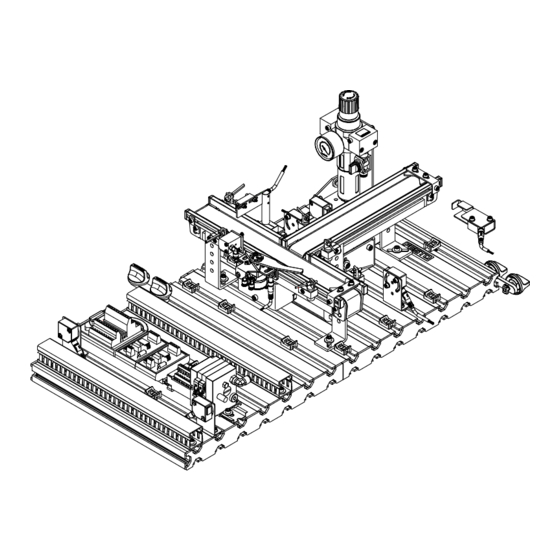
5. Aufbau und Funktion 5.1.2 Aufbau mit Folgestation(en) Aufbau der Station Trennen mit Folgestation(en) Die Stopper am Ende der Transportbänder sind demontiert. © Festo Didactic GmbH & Co. KG • 696682... -
Page 23: Funktion
Werkstück wird zur Sperre transportiert. 2. Der Reflexlichttaster vor der Sperre erkennt das Werkstück, der Bandmotor Transportband 1 wird ausgeschaltet. 3. Über den Reflexlichttaster oberhalb der Sperre erfolgt die Unterscheidung des Werkstückes. © Festo Didactic GmbH & Co. KG • 696682... - Page 24 Bandmotor 1 ausgeschaltet und der Leuchtmelder „Werkstück an Abholstelle“ eingeschaltet. • Steht das Sensorsignal “Puffer voll“ nach 4 s noch an, wird der Bandmotor 2 ausgeschaltet und der Leuchtmelder “Puffer voll“ eingeschaltet. © Festo Didactic GmbH & Co. KG • 696682...
-
Page 25: Modul Unterscheiden
SPS mit Analogsignalverarbeitung zugeführt werden. Hinweis Abmessungen Werkstücke Werkstücktyp Außenhöhe (mm) Innenhöhe (mm) Werkstück “Grundkörper“ Silber 25,0 22,5 25,0 22,5 Schwarz 22,5 20,0 Werkstück “Gehäuse“ Silber 23,0 10,0 23,0 10,0 Schwarz 23,0 10,0 © Festo Didactic GmbH & Co. KG • 696682... -
Page 26: Modul Verzweigen
Transportband 2, zur Abholstelle Bandende Transportband 1 bzw. zu einer nachfolgenden Station. Der Nachweis der Werkstücke am Bandanfang Transportband 2 und am Bandende Transportband 1 erfolgt durch Einweg-Lichtschranken. Der Antrieb der Transportbänder erfolgt durch Gleichstrom-Getriebemotoren. © Festo Didactic GmbH & Co. KG • 696682... -
Page 27: Modul Weiche, Pneumatisch
Über ein elektrisch betätigtes Ventil wird ein doppeltwirkender pneumatischer Schwenkantrieb angesteuert. Die Kraft wird über einen Schwenkflügel direkt auf die Abtriebswelle übertragen. Mit einem induktiven Näherungsschalter kann die Position des metallischen Auswerfers berührungslos abgefragt werden. © Festo Didactic GmbH & Co. KG • 696682... - Page 28 5. Aufbau und Funktion © Festo Didactic GmbH & Co. KG • 696682...
-
Page 29: Inbetriebnahme
• ein SPS Board • ein Netzgerät 24 V DC, 4,5 A • eine Druckluftversorgung mit 600 kPa (6 bar), Saugleistung ca. 50 l/min • einen PC mit installierter SPS Programmiersoftware © Festo Didactic GmbH & Co. KG • 696682... -
Page 30: Mechanischer Aufbau
6. Inbetriebnahme 6.2.1 Montage von Profilplatte und Bedienpult Mechanischer Aufbau 2 (4x) 4 (4x) 5 (2x) Profilplatte Hammermutter M6-32 (4x) Wagen Zylinderschraube M6x10 (4x) Blechschraube 3,5x9 (2x) Bedienpult © Festo Didactic GmbH & Co. KG • 696682... -
Page 31: Sensoren Justieren
5. Kontrollieren Sie die Positionierung des Näherungsschalters durch wiederholte Probeläufe des Zylinders (ein-/ausfahren). Dokumente • Datenblätter Näherungsschalter SIEN-M5B-PS-S-L (150371) im Verzeichnis Deutsch\12_Trennen\Datenblaetter der mitgelieferten CD-ROM. • Bedienungsanleitungen SIEN-M5B-PS-S-L (150371) im Verzeichnis Deutsch\12_Trennen\Bedienungsanleitungen der mitgelieferten CD-ROM. © Festo Didactic GmbH & Co. KG • 696682... -
Page 32: Reflex-Lichttaster (Modul Verzweigen, Werkstücknachweis)
Dokumente • Datenblätter Lichtleitergerät SOEG_L (165327) und Lichtleiter Reflex SOEZ-RT (165358) im Verzeichnis Deutsch\12_Trennen\Datenblaetter der mitgelieferten CD-ROM. • Bedienungsanleitungen Lichtleitergerät (369669) und Lichtleiter Reflex (369682) im Verzeichnis Deutsch\12_Trennen\Bedienungsanleitungen der mitgelieferten CD-ROM. © Festo Didactic GmbH & Co. KG • 696682... -
Page 33: Reflex-Lichttaster (Modul Unterscheiden, Werkstückidentifikation)
Alle Werkstücke “Gehäuse“ müssen sicher erkannt werden. Dokumente • Datenblätter Reflex-Lichttaster SOEG_RTD_Q20 (537757) im Verzeichnis Deutsch\12_Trennen\Datenblaetter der mitgelieferten CD-ROM. • Bedienungsanleitungen Reflex-Lichttaster mit Analogausgang (675805) im Verzeichnis Deutsch\12_Trennen\Bedienungsanleitungen der mitgelieferten CD-ROM. © Festo Didactic GmbH & Co. KG • 696682... -
Page 34: Einweg-Lichtschranke (Modul Verzweigen, Werkstücknachweis)
Dokumente • Datenblätter Lichtleitergerät SOEG_L (165327) und Lichtleiter Einweg SOEZ-SE (165360) im Verzeichnis Deutsch\12_Trennen\Datenblaetter der mitgelieferten CD-ROM. • Bedienungsanleitungen Lichtleitergerät (369669) und Lichtleiter Einweg (369684) im Verzeichnis Deutsch\12_Trennen\Bedienungsanleitungen der mitgelieferten CD-ROM. © Festo Didactic GmbH & Co. KG • 696682... -
Page 35: Sichtprüfung
• die elektrischen Anschlüsse • den korrekten Sitz und den Zustand der Druckluftanschlüsse • die mechanischen Komponenten auf sichtbare Defekte (Risse, lose Verbindungen usw.) Beseitigen Sie entdeckte Schäden vor dem Start der Station! © Festo Didactic GmbH & Co. KG • 696682... -
Page 36: Kabelverbindungen
Bedienpults. 3. SPS Board – Netzgerät Stecken Sie die 4 mm Sicherheitsstecker in die Buchsen des Netzgerätes. 4. PC – SPS Verbinden Sie Ihren PC durch ein Programmierkabel mit der SPS. © Festo Didactic GmbH & Co. KG • 696682... -
Page 37: Pneumatischer Anschluss
Deutsch\12_Trennen\Bedienungsanleitungen der mitgelieferten CD-ROM. • Die Stationen werden über ein Netzgerät mit 24 V Gleichspannung (max. 5 A) Spannungsversorgung versorgt. • Die Spannungsversorgung der kompletten Station erfolgt über das SPS Board. © Festo Didactic GmbH & Co. KG • 696682... -
Page 38: Sps Programm Laden
Sie können den Betriebsartenschalter loslassen. Er geht dabei selbsttätig in die STOP Stellung. – Die SPS ist urgelöscht und zum Laden der Programme bereit. 6. Betriebsartenschalter in Position STOP 7. Starten Sie die Programmiersoftware © Festo Didactic GmbH & Co. KG • 696682... - Page 39 Ihre SPS: – SPS 313C – SPS 313C 2DP – SPS 314 – SPS 315 2DP 10. Wählen Sie das Projekt 12TR_AS oder 12TR_KFA (AS = Ablaufsprache, KFA = KOP/FUP/AWL) © Festo Didactic GmbH & Co. KG • 696682...
- Page 40 6. Inbetriebnahme 11. Laden Sie das Projekt in die Steuerung Zielsystem Laden Folgen Sie den Anweisungen auf dem Bildschirm 12. Betriebsartenschalter in Position RUN © Festo Didactic GmbH & Co. KG • 696682...
-
Page 41: Siemens Steuerung Mit Analog-Baugruppe
Sie können den Betriebsartenschalter loslassen. Er geht dabei selbsttätig in die STOP Stellung. – Die SPS ist urgelöscht und zum Laden der Programme bereit. 6. Betriebsartenschalter in Position STOP 7. Starten Sie die Programmiersoftware © Festo Didactic GmbH & Co. KG • 696682... - Page 42 Dearchivieren: Die dearchivierten Daten wurden im Projektverzeichnis abgelegt. OK Dearchivieren: Die folgenden Objekte wurden dearchiviert. Sollen diese jetzt geöffnet werden? Ja 9. Wählen Sie das Projekt 12TR_AS_Analog oder 12TR_KFA_Analog. (AS = Ablaufsprache, KFA = KOP/FUP/AWL) © Festo Didactic GmbH & Co. KG • 696682...
- Page 43 6. Inbetriebnahme 10. Laden Sie das Projekt in die Steuerung Zielsystem Laden Folgen Sie den Anweisungen auf dem Bildschirm 11. Betriebsartenschalter in Position RUN © Festo Didactic GmbH & Co. KG • 696682...
-
Page 44: Festo Steuerungen
6. Inbetriebnahme 6.8.3 Festo Steuerungen • Steuerungen: Festo FEC FC640, IPC CPU HC02, IPC CPU HC20 • Programmiersoftware: Festo FST Version 4.02 1. PC und Steuerung mit dem Programmierkabel TTL-RS232 verbinden 2. Netzgerät einschalten 3. Druckluftversorgung einschalten 4. NOT-AUS Taster entriegeln (falls vorhanden) 5. - Page 45 6. Inbetriebnahme 8. Kompilieren Sie das Projekt Projekt Alles übersetzen 9. Laden Sie das Projekt in die Steuerung Online Projekt laden Folgen Sie den Anweisungen auf dem Bildschirm © Festo Didactic GmbH & Co. KG • 696682...
-
Page 46: Allen Bradley Steuerungen
Configure Drivers… in der Liste “Available Driver Types“ die Einstellung “RS-232 DF1 devices“ wählen und auf Add New… klicken Meldung (“Choose a name…“, Vorgabe: AB_DF1-1) mit OK bestätigen Auto configure Close © Festo Didactic GmbH & Co. KG • 696682... - Page 47 Wenn die COMM 0.-LED erlischt, ist der Speicher der SPS gelöscht und zum Laden der Programme bereit. 6. Öffnen Sie die Projektdatei 12TR_K im Verzeichnis Quellen\ SPS Programme\Release C\ML 1500 der mitgelieferten CD-ROM. © Festo Didactic GmbH & Co. KG • 696682...
- Page 48 Steuerung auswählen, auf Download klicken. Bestätigen Sie die nachfolgenden Meldungen ("Revision note","…sure to proceed with Download?", "…want to go online?") mit Ja bzw. OK 8. Betriebsartenschalter in Position REM bzw. RUN © Festo Didactic GmbH & Co. KG • 696682...
-
Page 49: Mitsubishi/Melsec Steuerungen
SPS Programme\Release C\FX1N der mitgelieferten CD-ROM. Extras Project Restore … Projektdatei auswählen (CD ROM: Quellen\SPS Programme\Release C\FX1N) 12TR_AS.pcd Öffnen Zielverzeichnis auswählen OK nachfolgende Meldung (“After saving,…”)mit OK bestätigen 7. Kompilieren Sie das Projekt © Festo Didactic GmbH & Co. KG • 696682... - Page 50 6. Inbetriebnahme Project Rebuild all 8. Laden Sie das Projekt in die Steuerung Project Transfer Download to PLC… nachfolgende Meldungen ("Transfer to PLC", ….),mit OK bestätigen 9. Betriebsartenschalter in Position RUN © Festo Didactic GmbH & Co. KG • 696682...
-
Page 51: Ablauf Starten
Transportband 1 belegt ist. Das Werkstück entfernen und mit dem Start-Taster quittieren. • Der Leuchtmelder “Puffer voll“ ist an, wenn sich 6 Werkstücke auf dem Transportband 2 befinden. Die Werkstücke entfernen und mit dem Start-Taster quittieren. © Festo Didactic GmbH & Co. KG • 696682... -
Page 52: Kombination Von Stationen
• Die Station Trennen verfügt über zwei StationLink Empfänger. 6.10.2 Hardwareanpassungen Stopper am Bandende Wird die Station Trennen mit einer bzw. zwei Folgestationen betrieben, muss der Stopper am Ende des jeweiligen Transportbandes demontiert werden. © Festo Didactic GmbH & Co. KG • 696682... -
Page 53: Wartung
• die Linsen der optischen Sensoren, der Faseroptiken sowie Reflektoren • die aktive Fläche des Näherungsschalters • die gesamte Station mit einem weichen, fuselfreien Tuch oder Pinsel gereinigt werden. Es dürfen keine aggressiven oder scheuernde Reinigungsmittel verwendet werden. © Festo Didactic GmbH & Co. KG • 696682... - Page 54 7. Wartung © Festo Didactic GmbH & Co. KG • 696682...
-
Page 55: Inhalt Der Cd-Rom
CPV Ventilinsel 165 100 Lichtleiter, Einweg 369 684 Lichtleiter, Reflex 369 682 Lichtleitergerät 369 669 Lichtschranke, Empfänger 369 662 Lichtschranke, Sender 369 679 Pneumatische Zylinder 391 172 Reflex-Lichttaster SOEG 675 805 © Festo Didactic GmbH & Co. KG • 696682... -
Page 56: Datenblätter
175 827 Pneumatik-Zylinder AEVC-12 188 083 Schalldämpfer UC-M7 161 418 Steckdose mit Anschlusskabel SIM-M8-3GD 159 420 Steckdose mit Anschlusskabel SIM-M8-4GD 158 960 Steckverschraubung 186 117 Steckverschraubung 153 332 Steckverschraubung 153 333 © Festo Didactic GmbH & Co. KG • 696682... -
Page 57: Aktualisierungen
Aktualisierungen ® Aktuelle Informationen und Ergänzungen zur Technischen Dokumentation der MPS Stationen finden Sie im Internet unter der Adresse: http://www.festo-didactic.de/Services > MPS © Festo Didactic GmbH & Co. KG • 696682... - Page 58 Aktualisierungen © Festo Didactic GmbH & Co. KG • 696682...
-
Page 59: Contents
Diffuse sensor (Branching module, detection of workpieces)___________ 86 6.3.3 Diffuse sensor (Differentiation module, identification of workpieces) ____ 87 6.3.4 Through-beam sensor (Branching module, detection of workpieces) ____ 88 Visual check __________________________________________________ 89 © Festo Didactic GmbH & Co. KG • 696682... - Page 60 6.10.1 Networking__________________________________________________ 106 6.10.2 Hardware modifications _______________________________________ 106 Maintenance ________________________________________________ 107 Content of the CD-ROM ______________________________________________ 109 Circuit diagrams______________________________________________ 109 Programming ________________________________________________ 109 Operating instructions_________________________________________ 109 Data sheets _________________________________________________ 110 Updates _________________________________________________________ 111 © Festo Didactic GmbH & Co. KG • 696682...
-
Page 61: Introduction
Introduction The Festo Didactic Learning System for Automation is designed to meet a number of different training and vocational requirements. The systems and stations of the ® Modular Production System (MPS ) facilitate industry-orientated vocational and further training and the hardware consists of didactically suitable industrial components. -
Page 62: Training Contents
• PLC programming Programming of counters – Programming of an intermediate buffer for workpiece parameters – Programming of an operational section – Programming of a RESET sequence – © Festo Didactic GmbH & Co. KG • 696682... -
Page 63: Important Notes
Duty of trainees • read the chapter on safety and the cautionary notes in this manual and, • observe the basic regulations regarding operational safety and the prevention of accidents. © Festo Didactic GmbH & Co. KG • 696682... -
Page 64: Risks Involved In Dealing With The Modular Production System
® The MPS is to be used only: • for its intended purpose and • in an absolutely safe conditions. Faults impairing safety must be rectified immediately! © Festo Didactic GmbH & Co. KG • 696682... -
Page 65: Warranty And Liability
• Incorrectly carried out repairs • Catastrophies as a result of foreign bodies and vis major. Festo Didactic herewith rules out any liability for damage or injury to trainees, the training company and/or other third parties which may occur during the use/operation of the system other than purely in a training situation, unless such damage has been caused intentionally or due to gross negligence by Festo Didactic. - Page 66 1. Introduction © Festo Didactic GmbH & Co. KG • 696682...
-
Page 67: Notes On Safety
Mechanics • Securely mount all components on the plate. • No manual intervention unless the machine is at rest. © Festo Didactic GmbH & Co. KG • 696682... - Page 68 2. Notes on safety © Festo Didactic GmbH & Co. KG • 696682...
-
Page 69: Technical Data
(PR) Processing (BE) Handling (HA) Buffer (PU) Pick&Place (PP) FluidicMuscle Press (FP) Separating (TR) Storing (LA) Robot Assembly* (MO/HS) * Assembly with Punching / ** Sorting DP / *** Distributing AS-Interface © Festo Didactic GmbH & Co. KG • 696682... - Page 70 3. Technical data © Festo Didactic GmbH & Co. KG • 696682...
-
Page 71: Transport/Unpacking/Scope Of Delivery
The container must be transported on a suitable fork lift truck at all times and must be secured against tipping or falling off. The carrier and Festo Didactic are to be notified immediately of any damage caused during transport. Unpacking Carefully remove the padding material in the container box when unpacking the station. - Page 72 4. Transport/Unpacking/Scope of delivery © Festo Didactic GmbH & Co. KG • 696682...
-
Page 73: Design And Function
(0° staggered) or be sorted out onto conveyor belt 2 or be transported to a further subsequent station (90° staggered). The workpieces must proceed individually so as not to impair the switching functions of the branch. © Festo Didactic GmbH & Co. KG • 696682... - Page 74 The Separating station consists of the following components: • Differentiation module • Branching module • Sorting gate module • Profile plate • Trolley • Control console • PLC board Separating station with trolley, control console and PLC board © Festo Didactic GmbH & Co. KG • 696682...
-
Page 75: Setup For Use As An Individual Station
5.1.1 Setup for use as an individual station Setup of Separating station for use as an individual station or last station of a system The stoppers are fitted at the end of the conveyor belts. © Festo Didactic GmbH & Co. KG • 696682... -
Page 76: Setup With Subsequent Station(S)
5. Design and function 5.1.2 Setup with subsequent station(s) Setup of Separating station with subsequent station(s) The stoppers at the end of the conveyor belts are removed. © Festo Didactic GmbH & Co. KG • 696682... -
Page 77: Function
2. The conveyor belt motor 1 is switched off, if the workpiece is detected by the diffuse sensor in front the stopper. 3. The differentiation of the workpiece takes places by the diffuse sensor above the stopper. © Festo Didactic GmbH & Co. KG • 696682... - Page 78 2 s. The indicator light “workpiece at pick-up point” is switched on. • The conveyor motor 2 is switched off, if the sensor signal “buffer full” is still applied after 4 s. The indicator light “buffer full” is switched on. © Festo Didactic GmbH & Co. KG • 696682...
-
Page 79: Differentiation Module
Size of workpieces Type of workpiece Total height (mm) Interior height (mm) workpiece “cylinder body“ silver 25,0 22,5 25,0 22,5 black 22,5 20,0 workpiece “housing“ silver 23,0 10,0 23,0 10,0 black 23,0 10,0 © Festo Didactic GmbH & Co. KG • 696682... -
Page 80: Branching Module
Workpieces at the start of the conveyor belt 2 and at the end of conveyor belt 1 are detected by means of optical proximity sensors with fibre-optic cables. The conveyor belts are driven by DC-gear motors. © Festo Didactic GmbH & Co. KG • 696682... -
Page 81: Sorting Gate Module, Pneumatic
A double acting rotary drive cylinder causes the 45° rotation of a mounted ejector. The power is directly transfered to the drive shaft by a swiveling wing. End position sensing of the ejector is effected by a proximity sensor. © Festo Didactic GmbH & Co. KG • 696682... - Page 82 5. Design and function © Festo Didactic GmbH & Co. KG • 696682...
-
Page 83: Commissioning
• A power supply unit 24 V DC, 4.5 A • A compressed air supply of 6 bar (600 kPa), approx. suction capacity of 50 l/min • A PC with installed PLC programming software © Festo Didactic GmbH & Co. KG • 696682... -
Page 84: Mechanical Set Up
6.2.1 Assembling profile plate and control console Mechanical set up 2 (4x) 4 (4x) 5 (2x) Profile plate T-head nut M6 x-32 (4x) Trolley Socket head screw M6x10 (4x) Screw 3.5x9 (2x) Control console © Festo Didactic GmbH & Co. KG • 696682... -
Page 85: Adjust Sensors
Proximity sensor, inductive SIEN-M5B-PS-S-L (150371) in the directory English\12_Separating\Data sheets on the CD-ROM supplied. • Operating instructions Proximity sensor, inductive SIEN-M5B-PS-S-L (150371) in the directory English\12_Separating\Operating instructions on the CD-ROM supplied. © Festo Didactic GmbH & Co. KG • 696682... -
Page 86: Diffuse Sensor (Branching Module, Detection Of Workpieces)
(165358) in the directory English\12_Separating\Data sheets on the CD-ROM supplied. • Operating instructions Fibre optic device (369669) and fibre optic cable diffuse (369682) in the directory English\12_Separating\Operating instructions on the CD-ROM supplied. © Festo Didactic GmbH & Co. KG • 696682... -
Page 87: Diffuse Sensor (Differentiation Module, Identification Of Workpieces)
Diffuse sensor SOEG_RTD_Q20 (537757) in the directory English\12_Separating\Data sheets on the CD-ROM supplied. • Operating instructions Diffuse sensor with analog output (675805) in the directory English\12_Separating\Operating sheets on the CD-ROM supplied. © Festo Didactic GmbH & Co. KG • 696682... -
Page 88: Through-Beam Sensor (Branching Module, Detection Of Workpieces)
(165360) in the directory English\12_Separating\Data sheets on the CD-ROM supplied. • Operating instructions Fibre optic device (369669) and fibre optic cable through-beam (369684) in the directory English\12_Separating\Operating instructions on the CD-ROM supplied. © Festo Didactic GmbH & Co. KG • 696682... -
Page 89: Visual Check
• The correct installation and condition of the compressed air connections • The mechanical components for visual defects (tears, loose connections etc.) Eliminate any damage detected prior to starting up the station! © Festo Didactic GmbH & Co. KG • 696682... -
Page 90: Cable Connections
3. PLC board – power supply unit Plug the 4 mm safety plugs into the sockets of the power supply unit. 4. PC – PLC Connect your PC to the PLC by means of a programming cable. © Festo Didactic GmbH & Co. KG • 696682... -
Page 91: Pneumatic Connection
• The stations are supplied with 24 V DC voltage (max. 4.5 A) via a power supply Voltage supply unit. • The voltage supply of the complete station is effected via the PLC board. © Festo Didactic GmbH & Co. KG • 696682... -
Page 92: Loading The Plc Program
When the STOP LED comes on permanently the memory reset is completed. – The PLC is ready for program download. 6. mode selector switch in STOP position 7. Start the PLC programming software © Festo Didactic GmbH & Co. KG • 696682... - Page 93 – PLC 313C – PLC 313C 2DP – PLC 314 – PLC 315 2DP 10. Select the project 12TR_AS or 12TR_KFA (AS = sequential function chart, KFA = Ladder diagram/Function block diagram/Instruction list) © Festo Didactic GmbH & Co. KG • 696682...
- Page 94 6. Commissioning 11. Download the project to the controller Download Follow the instructions on the screen 12. Turn the mode selector switch of the CPU to RUN position © Festo Didactic GmbH & Co. KG • 696682...
-
Page 95: Siemens Controller With Analog Module
PLC via menu "PLC / Display Accessible Nodes" and deleting all blocks in the block folder. 6. mode selector switch in STOP position 7. Start the PLC programming software © Festo Didactic GmbH & Co. KG • 696682... - Page 96 Retrieve: The following objects were retrieved. Do you want to open these now? Yes 9. Select the project 12TR_AS_Analog or 12TR_KFA_Analog (AS = sequential function chart, KFA = Ladder diagram/Function block diagram/Instruction list) © Festo Didactic GmbH & Co. KG • 696682...
- Page 97 6. Commissioning 10. Download the project to the controller Download Follow the instructions on the screen 11. Turn the mode selector switch of the CPU to RUN position © Festo Didactic GmbH & Co. KG • 696682...
-
Page 98: Festo Controller
6. Commissioning 6.8.3 Festo controller • Controller: Festo FEC FC640, IPC CPU HC02, IPC CPU HC20 • Programming software: Festo FST Version 4.02 1. Connect PC and PLC using the TTL-RS232 programming cable 2. Switch on power supply unit 3. Switch on the compressed air supply 4. - Page 99 6. Commissioning 8. Compile the project Project Build Project 9. Download the project to the controller Online Download Projekt Follow the instructions on the screen © Festo Didactic GmbH & Co. KG • 696682...
-
Page 100: Allen Bradley Controller
Communications Configure Drivers… select the setting “RS-232 DF1 devices“ from the list “Available Driver Types“ and click Add New… confirm note (“Choose a name…“, default: AB_DF1-1) with OK Auto configure Close © Festo Didactic GmbH & Co. KG • 696682... - Page 101 When the COMM 0.- LED stops blinking the memory reset is completed. – The PLC is ready for program download. 6. Open the file 12TR_K from the directory Sources\PLC Programs\Release C\ ML 1500 of the CD-ROM supplied © Festo Didactic GmbH & Co. KG • 696682...
- Page 102 Download Confirm the following notes (“Revision note","…sure to proceed with Download?", "…want to go online?") with Yes or OK 8. Turn the mode selector switch of the CPU to RUN position © Festo Didactic GmbH & Co. KG • 696682...
-
Page 103: Mitsubishi/Melsec Controller
Extras Project Restore … select a project file (CD ROM: Sources\PLC Programs\Release C\FX1N) 12TR_AS.pcd Open Select destination directory OK Confirm the following note (“After saving,…”) with OK 7. Compile the project © Festo Didactic GmbH & Co. KG • 696682... - Page 104 8. Download the project to the controller Project Transfer Download to PLC… Confirm the following notes ("Transfer to PLC", ….) with OK 9. Turn the mode selector switch of the CPU to RUN position © Festo Didactic GmbH & Co. KG • 696682...
-
Page 105: Starting The Sequence
1 is occupied. Remove the workpiece and confirm by pressing the START pushbutton. • The indicator light “buffer full” is illuminated if 6 workpieces are on the conveyor belt 2. Remove the workpieces and confirm by pressing the START pushbutton. © Festo Didactic GmbH & Co. KG • 696682... -
Page 106: Combination Of Stations
Modification of the conveyor belt If the Separating station is operated in combination with one or two downstream stations, remove the mechanical stopper at the end of the corresponding conveyor belt. © Festo Didactic GmbH & Co. KG • 696682... -
Page 107: Maintenance
• The lenses of the optical sensors, the fibre-optics and reflectors • The active surface of the proximity sensor • The entire station Do not use aggressive or abrasive cleaning agents. © Festo Didactic GmbH & Co. KG • 696682... - Page 108 7. Maintenance © Festo Didactic GmbH & Co. KG • 696682...
-
Page 109: Content Of The Cd-Rom
369 669 Fibre-optic cable, diffuse 369 682 Fibre-optic cable, through-beam 369 684 Pneumatic cylinders 391 172 Through-beam sensor, receiver 369 662 Through-beam sensor, transmitter 369 679 Diffuse sensor SOEG 675 805 © Festo Didactic GmbH & Co. KG • 696682... -
Page 110: Data Sheets
175 827 Pneumatic cylinder AEVC-12 188 083 Fitting 186 117 Fitting 153 332 Fitting 153 333 Silencer UC-M7 161 418 Socket connector cable SIM-M8-3GD 159 420 Socket connector cable SIM-M8-4GD 158 960 © Festo Didactic GmbH & Co. KG • 696682... -
Page 111: Updates
Updates Up-to-date information and additional documents for the Technical documentation ® of the MPS stations please find at the address: http://www.festo-didactic.com/ Services > MPS © Festo Didactic GmbH & Co. KG • 696682... - Page 112 Updates © Festo Didactic GmbH & Co. KG • 696682...
Need help?
Do you have a question about the MPS Station and is the answer not in the manual?
Questions and answers