Table of Contents
Advertisement
Quick Links
Advertisement
Table of Contents

Related Manuals for JHCTech WPPC-H1780T


Summary of Contents for JHCTech WPPC-H1780T
- Page 1 User’s Manual WPPC-H1780T WPPC-H1580T User’s Manual Ver.:A0.1 Date:29, Oct., 2020...
- Page 2 User’s Manual Version Note Ver. Note Date Writer A0.1 first publish 20201029 Echo...
- Page 3 Microsoft Windows and MS-DOS are registered trademarks of Microsoft Corp. RTL is a trademark of Realtek Semi-Conductor Co., Ltd. All other product names or trademarks are properties of their respective owners. For more information on this and other JHC products, please visit our websites at: http://www.jhctech.com.cn...
- Page 4 User’s Manual Product Warranty (2 years) JHC warrants to you, the original purchaser, that each of its products will be free from defects in materials and workmanship for two years from the date of purchase. This warranty does not apply to any products which have been repaired or altered by persons other than repair personnel authorized by JHC, or which have been subject to misuse, abuse, accident or improper installation.
- Page 5 Technical Support and Assistance Step 1. Visit the JHC web site at www.jhctech.com.cn where you can find the latest information about the product. Step 2. Contact your distributor, sales representative, or JHC’s customer service center for technical support if you need additional assistance.
-
Page 6: Table Of Contents
User’s Manual CONTENTS General Information ......................1 1.1 Introduction ............................ 2 1.2 Features............................2 1.3 Specifications ..........................3 1.3.1 General ..........................3 1.3.2 Display ..........................3 1.3.3 Ethernet ..........................3 1.3.4 Power Consumption......................3 1.4 Environmental Specifications ....................... 4 1.5 Order Information ......................... 4 1.6 Mechanical Specifications ...................... - Page 7 User’s Manual 2.4.1 HDD/SSD Installation ......................15 2.4.2 Installing mSATA ....................... 16 2.4.3 Installing Mini PCIe ......................17 BIOS Setup ......................... 18 3.1 BIOS Description ......................... 19 3.1.1 Entering the Setup Utility ....................19 3.2 BIOS parameter settings ......................20 3.2.1 BIOS Navigation Keys .......................
-
Page 8: General Information
User’s Manual General Information... -
Page 9: Introduction
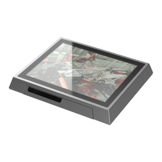
User’s Manual 1.1 Introduction WPPC-H1780T/WPPC-H1580T is a new product developed by JHC. WPPC-H1780T is a rugged, super- reliable, fanless embedded waterproof panel PC. The front panel is made of SUS304 stainless steel. The back cover is made of a 3.0mm 5052 aluminum alloy, which can meet both CPU thermal dissipation ®... -
Page 10: Specifications
Display Memory: Shared system memory Resolution: VGA 1900x1200@60Hz; HDMI 1920*1080@60Hz 1.3.3 Ethernet ® Chipset: 2*Intel I210AT Ethernet controllers Speed: 10/100/1000 Mbps Integrated Interface: 2*RJ45 1.3.4 Power Consumption Power Consumption: TDP 12V/2.5A (WPPC-H1780T) TDP 12V/1.62A (WPPC-H1580T) Power Supply: DC 9~36V,D-Jack w/ M8... -
Page 11: Environmental Specifications
Introduction Industrial Waterproof Panel PC, Intel® Baytrail Celeron J1900 CPU, 17”TFT LCD, Resistive touch, 1*HDMI, 1*VGA, 2*G-LAN, 2*COM, 1*Opt. ANT, WPPC-H1780T-T001 1*USB3.0, 3*USB2.0, 1*Mini PCIe , 1*Simple-swap 2.5”SATA bay, 1*mSATA, DC 9~36V Industrial Waterproof Panel PC, Intel® Baytrail Celeron J1900 CPU, 17”TFT LCD, Capacitive touch, 1*HDMI, 1*VGA, 2*G-LAN, 2*COM, 1*Opt. -
Page 12: Mechanical Specifications
User’s Manual 1.6 Mechanical Specifications The WPPC-H1780T/ WPPC-H1580T is industrial waterproof panel PC of JHCTECH, consists of a JHC ESBC single board computer (ECM-I715) and installed in the universal aluminum rectangular profile housing. Main Board Front (ECM-I715) Figure 1.1 Main Board Rear (ECM-I715) - Page 13 User’s Manual WPPC-H1780T/WPPC-H1580T Fornt Figure 1.3 WPPC-H1780T Dimension: Unit: mm Figure 1.4 WPPC-H1580T Dimension: Unit: mm Figure 1.5...
-
Page 14: Hardware Installation
User’s Manual Hardware Installation... -
Page 15: Introduction
The following sections show jumpers settings and the external connectors and pin assignments for applications. 2.2 Jumpers setting The WPPC-H1780T/WPPC-H1580T Box Computer has a number of jumpers that allows you to configure your system to suit your application. The table below shows the function of each of the board’s Jumpers:... -
Page 16: Ethernet Connector
`*2.5”SATA2 tray 2.3.1 Ethernet Connector The WPPC-H1780T/WPPC-H1580T is equipped with 2*Intel I211AT chips for 10/100/1000Mbps Ethernet controllers. The product provides 2*RJ45, with LED indicators on the front side to show its Active/Link status (Green LED) and Speed status (yellow LED). -
Page 17: Usb Connector
The USB device allows data exchange between your computer and a wide range of simultaneously accessible external Plug and Play peripherals. The WPPC-H1780T/WPPC-H1580T provides 1*USB3.0 gen2, 3*USB2.0. The USB interface can be disabled in the system BIOS setup. Table 2.2 for USB 3.0 pin assignments. -
Page 18: Vga
User’s Manual 2.3.3 VGA The WPPC-H1780T/WPPC-H1580T provides a standard VGA display port. They can support the most resolution up to 1900*1200@60Hz. Table 2.4 for VGA pin assignments. Figure 2. 6 Table 2.4: VGA Pin Assignments Signal Signal Signal VGA_z_R GND_RGB... -
Page 19: Com Connector
User’s Manual 2.3.5 COM Connector The WPPC-H1780T/WPPC-H1580T provides 2 serial ports of COM1/2/ by 2*D-sub 9-pin connectors. COM1/2 can be configured as RS232、RS422 or RS485 by BIOS setup. Table 2.6 for COM1/2 pin assignments. Figure 2. 1 Table 2.6: COM1/2 Serial Ports Pin Assignments... -
Page 20: Serial Ata Power
Signal Signal 2.3.8 Mini-PCIe Connector WPPC-H1780T/WPPC-H1580T provides a Mini PCIe. Mini PCIe interface with PCIe and USB signal, Install Mini PCI Express cards such as network cards or other cards that comply with the Mini PCI Express specifications into the Mini PCI Express slot. -
Page 21: Msata Connector
Figure 2. 12 2.3.10 LED The WPPC-H1780T/WPPC-H1580T panel has one power indicator, one hard disk indicator, three network connection status indicators, and three CPU operating temperature indicators. When the CPU operating temperature ≤85℃, the green light; When the CPU temperature is between 86℃ and 95℃, the yellow light is on, and when the CPU operating temperature is ≥96℃, the red light is on. -
Page 22: Installation
User’s Manual 2.4 Installation 2.4.1 HDD/SSD Installation Step 1: unscrew the 2 screws on the HDD/SSD bracket of the rear panel. Step 2: remove the HDD/SSD stent. Step 3: load the HDD/SSD into the bracket and tighten the 4 screws on the left and right sides to fix the HDD/SSD. -
Page 23: Installing Msata
User’s Manual Figure 2. 16 2.4.2 Installing mSATA Step 1: Unscrew the 29 screws on the back panel and remove the cover plate Step 2: Insert the corresponding mSATA module into the corresponding slot and fix it by locking the screw. -
Page 24: Installing Mini Pcie
User’s Manual Figure 2. 18 2.4.3 Installing Mini PCIe Step 1: The step here is the same as above chapter “2.4.2 Installing mSATA”, For details, please refer to the above chapter “2.4.2 Installing mSATA” Figure 2. 19... -
Page 25: Bios Setup
User’s Manual BIOS Setup... -
Page 26: Bios Description
User’s Manual 3.1 BIOS Description BIOS is the communication bridge between hardware and software. How to correctly set the BIOS parameters is crucial for the system to work stably and whether the system works at its best. This chapter describes how to change the system settings through the BIOS settings. Note: For the purpose of better product maintenance, the manufacture reserves the right to change the BIOS items presented in this manual. -
Page 27: Bios Parameter Settings
User’s Manual Figure 3.1 3.2 BIOS parameter settings When you start the Setup Utility, the main menu appears. The main menu of the Setup Utility displays a list of the options that are available. A highlight indicates which option is currently selected. Use the cursor arrow keys to move the highlight to other options. -
Page 28: Bios Navigation Keys
User’s Manual 3.2.1 BIOS Navigation Keys Enter the SETUP settings interface, The BIOS navigation keys are listed below: Table 3.1: The BIOS navigation keys FUNCTION Exit the current menu ↑↓→← Scrolls through the items on a menu Change Opt. Enter Select General Help Previous Values... -
Page 29: Advanced Menu
User’s Manual BIOS Vendor (American Megatrends) This item shows the information of the BIOS vendor. BIOS ID (JH715A14) This item shows the information of the BIOS version. OS Selection (Windows 7) This item shows the OS Selection. Build Date and Time (02/05/2018/ 19:26:45) This item shows the information of the BIOS build date and time. - Page 30 User’s Manual ▶ ACPI Settings The item in the menu shows the highest ACPI sleep state when the system enters suspend. Figure 3.4 ACPI Sleep State Suspend Disabled: Shut down system sleep S3:Suspend to RAM This item allows user to enter the ACPI S3 (Suspend to RAM) Sleep State (default). Press <Esc>...
- Page 31 User’s Manual Figure 3.5 Serial Port 1 Configuration: Serial Port 1 Settings Serial Port 2 Configuration: Serial 2 Settings Serial Port 3 Configuration: Serial Port 3 Settings Serial Port 4Configuration: Serial Port 4 Settings 8-bit TTL GPIO input and output settings Serial Port 1 Configuration Figure 3.6...
- Page 32 User’s Manual Serial Port This item is used to set the serial interface to be turned on or off. The setting value is [Enabled] [Disabled] Device Setting (Read Only) This item displays the interrupt and address of the serial port. Change Setting Set port interrupt and address of the serial port.
- Page 33 User’s Manual Figure 3.8 Serial Port 5-10Configuration Serial Port 5-10 Configuration is the same as above ▶ H/W Monitor PC Health Status This item is used for hardware security detection. The BIOS will display the current CPU and system temperature. Figure 3.9...
- Page 34 User’s Manual ▶ S5 RTC Wake Settings Figure 3.10 Wake system from S5 This item is used to set whether to power on regularly. The setting value is [Enabled] [Disabled]. If you select [Enabled], set the hour, minute, and second in the pop-up options. ▶...
- Page 35 User’s Manual Console Redirection Use this item to Serial Port Console Redirection Press <Esc> to return to the Advanced Menu page. ▶ CPU Configuration This item in the menu shows the information of the CPU. Figure 3.12 Socket 0 CPU Information This item contains detailed information about the CPU, including the CPU manufacturer, model, frequency, L1 cache size, and L2 cache size.
- Page 36 User’s Manual return a value greater than 3. Because return values greater than 3 may cause some operating system wrong, generally set this option to [Disabled] on Windows systems for better overclocking. The default value is [Disabled]. Execute Disabled Bit The Execution Disable bit is a hardware feature of the Intel CPU that enables the CPU to avoid certain malicious attacks based on buffer overflow viruses.
- Page 37 User’s Manual Figure 3.13 CPU C state Report Whether to enable the CPU power status report, the setting values are: [Disabled], [Enabled]. When set to Enabled, the option Max CPU C-state appears and the Max CPU C-state value can be set. ▶...
- Page 38 User’s Manual Serial-ATA(SATA) This item allows you to enable or disable serial-ATA. SATA Speed Support This item shows the speed of support SATA. Press <Esc> to return to the Advanced Menu page. SATA ODD Port This item indicates which SATA port is set as the optical drive port. SATA Mode This item is used to set the operating mode of the SATA.
- Page 39 User’s Manual CSM Support Compatibility Support Module, which is a compatibility support module, is a special module of UEFI and provides compatibility support for systems that do not support UEFI. GateA20 Active This item indicates whether to disable GA20 through the BIOS server or keep the activation status all the time.
- Page 40 User’s Manual Figure 3.16 Legacy USB Support This item is used to set the USB interface support. If you need to support USB devices under DOS, such as U disk, USB keyboard, etc., set this item to [Enabled] or [Auto]. Otherwise, select [Disabled]. USB 2.0 (EHCI) Support [Enabled]: Allows USB EHCI transport protocol with a maximum transfer rate of 480Mpbs [Disabled]: Disable the USB2.0 interface, the traditional transfer rate is 12Mpbs.
-
Page 41: Chipset Menu
User’s Manual This item sets the maximum delay time that the USB device reports to the primary controller. Mass Storage Devices This item is used to set the specific type of connected USB device. The setting value is [Auto][Floppy][Forced FDD][Hard Disk][CD-ROM], the default is Auto. 3.2.4 Chipset Menu The chipset menu items allow you to change the settings for the North Bridge chipset, South Bridge chipset and other system. - Page 42 User’s Manual Figure 3.18 Integrated Graphics Device This item indicates whether integrated graphics is enabled. Primary Display This item shows the main output display device when the system starts up. DVMT pre-AIIocated This item sets the memory size pre-assigned to the motherboard integrated graphics in DVMT mode. DVMT Total Gfx Mem This item shows how much dynamic memory is allocated to the integrated graphic in total.
- Page 43 User’s Manual Figure 3.19 Primary IGFX Boot Display This item sets IGFX main display device on POST stage, not affected by external graphics card, options are LVDS, CRT, HDMI. It defaults by VBIOS. Secondary IGFX Boot Display This item sets IGFX second display device on POST stage. LCD Panel Type This item sets resolution of the motherboard LVDS screen.
-
Page 44: Boot Menu
User’s Manual Figure 3.20 Restore AC Power Loss This item sets the power-on status after power-on. If Power Off is selected, you need to press the power button to power on after power-on. If Power On is selected, it will be powered on directly after power-on. If Last State is selected after power-on, it will be restored to the state before power-off. - Page 45 User’s Manual Setup Prompt Timeout This item sets the wait time for the Setup shortcut. If you do not press the Setup shortcut within the set time, it will continue to boot. Bootup Numlock State This item determines if the NumLock key is active or inactive at system start-up time. The default value is On, which is a digital lock on when the system starts.
-
Page 46: Security Menu
User’s Manual 3.2.6 Security Menu Scroll to this item and press <Enter> and view the following screen: Figure 3.23 3.2.7 Save & Exit Menu This page enables you to exit system setup after saving or without saving the changes. Figure 3.24 Save Changes and Exit This item enables you to save the changes that you have made and exit. -
Page 47: Updating The Bios
User’s Manual Discard Changes and Exit This item enables you to discard any changes that you have made and exit. Restore Defaults This item enables you to restore the system defaults. 3.3 Updating the BIOS The BIOS (Basic Input and Output System) Setup Utility displays the system’s configuration status and provides you with options to set system parameters. -
Page 48: Driver Installation
User’s Manual Driver Installation... -
Page 49: About The Software Dvd-Rom/Cd-Rom
User’s Manual The WPPC-H1780T/WPPC-H1580T comes with a CD-ROM that contains all drivers and utilities that meet your needs. 4.1 About the Software DVD-ROM/CD-ROM The support software DVD-ROM/CD-ROM that is included in the motherboard package contains all the drivers and utility programs needed to properly run the bundled products. Below you can find a brief description of each software program, and the location for your motherboard version. - Page 50 User’s Manual Drivers Tab Table 4.1: Drivers Tab Setup Click the Setup button to run the software installation program. Select from the menu which software you want to install. The Browse CD button is the standard Windows command that Browse CD allows you to open Windows Explorer and show the contents of the support disk.
- Page 51 User’s Manual 2. Click Next. The following screen appears: Figure 4.1 3. Check the box next to the items you want to install. The default options are recom-mended. 4. Click Next run the Installation Wizard. An item installation screen appears: Figure 4.2 5.Follow the instructions on the screen to install the items.
- Page 52 User’s Manual bottom left to install the next driver. Figure 4.3 Windows 8/10 will appear below UAC (User Account Control) message after the system restart. You must select “Allow” to install the next driver. Continue this process to complete the drivers installation. Figure 4.4...
-
Page 53: Manual Installation
User’s Manual 4.3 Manual Installation Insert the disk in the DVD-ROM/CD-ROM drive and locate the PATH.DOC file in the root directory. This file contains the information needed to locate the drivers for your motherboard. Look for the chipset and motherboard model; then browse to the directory and path to begin installing the drivers. -
Page 54: System Resource
User’s Manual SYSTEM RESOURCE... -
Page 55: Wdt And Gpio
User’s Manual 5.1 WDT and GPIO 5.1.1 WDT /* ====================================================================== * void jhctech_init(); * function description: library initializated, This function must be called before calling other functions * parameter description: * creation date: ======================================================================*/ void jhctech_init(); /* ====================================================================== * void jhctech_init(); * function description:library release,Pair with jhctech_init, release the library's occupied resources when not needed * parameter description:... - Page 56 User’s Manual * parameter description: Return value:Return a byte (8 bit), each bit of the 8 bit corresponding to the level state of a GPIO pin. Return Bit7 Bit6 Bit5 Bit4 Bit3 Bit2 Bit1 Bit0 value GPIO PIN8 PIN7 PIN6 PIN5 PIN4 PIN3...
- Page 57 User’s Manual Bit =0, means output low level value Bit7 Bit6 Bit5 Bit4 Bit3 Bit2 Bit1 Bit0 GPIO pin PIN8 PIN7 PIN6 PIN5 PIN4 PIN3 PIN2 PIN1 * creation date: ======================================================================*/ void I715_MB_gpio_output(WORD port,BYTE value); /* ====================================================================== 1 * void I715_MB_gpio_init(); * function description:Motherboard gpio initialization function, need to be called once before * parameter description:...
- Page 58 User’s Manual * function description:WDT function * parameter:Time sets the dog feed time, the time value is 0-255, Setting 0 means to turn off the watchdog * creation date: ======================================================================*/ void I715_watchdog_set(int time); /* ====================================================================== * void I715_2nd_gpio_mode(int port,int mode); * function description:subcard input and output mode settings * parameter description:...
- Page 59 User’s Manual Note :The output value is valid only when the pin is in output mode. * creation date: ======================================================================*/ void I715_2nd_gpio_mode(int port,int mode); /*====================================================================== * void I715_2nd_gpio_output(int port,int level); * function description:subcard output high and low level *parameter descirption: parameter:port fill in GPIO number of the subcard, 1 or 2 level 8 bits of a byte, each bit controls a GPIO pin output value, Bit =1, means output high level...
- Page 60 User’s Manual /*====================================================================== * int I715_2nd_gpio_input(int port); * function description:read the motherboard GPIO input level * parameter description: Return value:return a byte (8 bit), each bit of the 8 bit corresponding to the level state of a GPIO pin Value=1, means high level Value=0, means low level Return value Bit7...
Need help?
Do you have a question about the WPPC-H1780T and is the answer not in the manual?
Questions and answers