Table of Contents
Advertisement
Quick Links
Advertisement
Table of Contents

Related Manuals for JHCTech KGEC-6300


Summary of Contents for JHCTech KGEC-6300
- Page 1 用户手册 User’s Manual KGEC-6300 Ver.: A0.1 Date:2020-09-11...
- Page 2 User’s Manual Version Note Ver. Note Date Writer A0.1 first publish 20200911 Echo Guo...
- Page 3 User’s Manual Copyright The documentation and the software included with this product are copy- righted 2020 by Shenzhen JHC Technology Development Co.,Ltd. All rights are reserved. Shenzhen JHC Technology Development Co.,Ltd. reserves the right to make improvements in the products described in this manual at any time without notice.
- Page 4 User’s Manual Product Warranty (2 years) JHC warrants to you, the original purchaser, that each of its products will be free from defects in materials and workmanship for 2 years from the date of purchase. This warranty does not apply to any products which have been repaired or altered by persons other than repair personnel authorized by JHC, or which have been subject to misuse, abuse, accident or improper installation.
- Page 5 Technical Support and Assistance Step 1. Visit the JHC web site at www.jhctech.com.cn where you can find the latest information about the product. Step 2. Contact your distributor, sales representative, or JHC’s customer service center for technical support if you need additional assistance.
-
Page 6: Table Of Contents
User’s Manual CONTENTS General Information ................... 4 1.1 Introduction ..........................5 1.2 Features ........................... 5 1.3 Specifications ........................... 7 1.3.1 General ............................7 1.3.2 Display ............................7 1.3.3 Ethernet ............................7 1.3.4 Power Consumption ........................7 1.4 Environmental Specifications ....................7 1.5 Order information ........................ - Page 7 User’s Manual 2.3.7 Mini PCIe ............................. 19 2.3.8 mSATA ............................20 2.3.9 PCI (T002) ..........................22 2.3.10 PCIeX4(T002) ........................22 2.3.15 LED ............................24 2.4 Installation ..........................25 2.4.1 mSATA installation........................25 2.4.2 Mini PCIe installation ........................26 2.4.3 PCI installation(T001/2) ......................26 2.4.4 PCIX4 installation(T001/2)...
- Page 8 User’s Manual 4.4 Utility Software Reference ...................... 54 SYSTEM RESOURCE ..................55 5.1 WDT and GPIO ........................56...
-
Page 9: General Information
User’s Manual General Information... -
Page 10: Introduction
User’s Manual 1.1 Introduction The KGEC-6300 is a new edge controller by JHC, and the mainboard and sub-board are designed with ® an all-in-one architecture without connection. The KGEC-6300 is equipped with Intel Skylake-S/ Kabylake-S Core I3/I5/I7 CPU, support for 1* DDR4 2133/2400Mhz, up to 16GB, and the 9th ®... - Page 11 User’s Manual Model No. KGEC-6300-S001 KGEC-6300-T001 KGEC-6300-T001 Specification ® ® ® Intel Skylake- Intel Skylake- Intel Skylake- S/Kabylake-S S/Kabylake-S S/Kabylake-S LGA1151 CPU LGA1151 CPU LGA1151 CPU ® ® ® Chipset Intel H110 Intel H110 Intel H110 Mermory 1*DDR4 最大16GB 1*DDR4 最大16GB 1*DDR4 最大16GB...
-
Page 12: Specifications
User’s Manual 1.3 Specifications 1.3.1 General CPU: Intel® Skylake-S/Kabylake-S Core I3/I5/I7 CPU System Memory: 1*DDR4, 2133/2400MHz, up to 16GB Watchdog Timer: 255-level interval timer, setup by software USB: 4*USB3.0, Type A Serial Ports: 2*RS232/422/485 with TVS isolated (DB9) Expansion Interface: 1*Mini PCIe with PCIe X1+USB signal, 1*SIM slot, support 1*4G/LTE/Wifi/BT/GPS 1*PCIe X4 slot with PCIe X1 signal (T001/2) 1*32bit-PCI, support motion control card, acceleration card and other functions card (T001/2) -
Page 13: Order Information
AC/DC power adapter, DC19V/6.32A 120W 1.6 Mechanical Specifications The KGEC-6300 edge controller is assembled by the splice of The OSBC (single-board computer STX- I952) and the Sub-card (ECX-257) of JHC, and installed in the universal aluminum rectangular profile housing. Among them, sub-card ECX-257 is only assembled in T002. - Page 14 User’s Manual STX-I952 Front Picture 1.1: STX-I952 Front STX-I952 Rear Picture 1.2: STX-I952 Rear ECX-257 Front (T002) Picture 1.3: ECX-257...
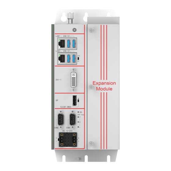
- Page 15 User’s Manual KGEC-6300-T002 Front Panel Picture 1.4: KGEC-6300-T002 Front Panel KGEC-6300-T002 Rear Panel Picture 1.5: KGEC-6300-T002 Rear Panel...
- Page 16 User’s Manual KGEC-6300-S001 Dimension: Unit: mm Picture 1.6 KGEC-6300-S001 Dimension KGEC-6300-T002 Dimension: Unit: mm Picture 1.7 KGEC-6300-T002 Dimension...
-
Page 17: Hardware Installation
User’s Manual Hardware Installation... -
Page 18: Introduction
2.2 Switches The KGEC-6300 edge controller has a number of switches inside the chassis that allows you to configure your system to suit your application. The table below shows the function of each of the board’s switches: Switcher... -
Page 19: At/Atx Power On Mode Selection
Picture 2.2: AT/ATX The KGEC-6300 provides an AT/ATX SW, which users can set Power-on mode by it. When you dial it at AT, it means power on by AC Power; When you dial it at ATX, it means power on by Power button. -
Page 20: Ethernet Connector
The rear panel contains the I/O interface: 1*PCIe X4 slot(T001/2) 1*32bit-PCI slot(T001/2) 2.3.1 Ethernet Connector The KGEC-6300 is equipped with 2*Intel® I210AT, supporting 10/100/1000Mbps rate adaptive. The Ethernet provides the standard RJ-45 interface. Table 2.1 provides a detailed description of pin assignment. -
Page 21: Usb
The USB device allows data exchange between your computer and a wide range of simultaneously accessible external Plug and Play peripherals. The KGEC-6300 provides 4*USB3.0, 1*USB2.0 for dongle. The USB interface can be disabled in the system BIOS setup. Table 2.2 for USB3.0 pin assignments. -
Page 22: Dvi-I
DATA2_P 2.3.4 DVI-I The KGEC-6300 provides a DVI-I display port with DVI-D and VGA signal. The DVI-D can support the most resolution up to 1920*1200@60Hz, The VGA can support the most resolution up to 2560*1600@ 60Hz. Table 2.5 for DVI-I pin assignments. -
Page 23: Power Input (Dc-In)
2.3.5 Power input (DC-IN) The KGEC-6300 provides a 2*2Pin Phoenix for DC 12-24V power input. The power input use a double- layer power socket, and the upper and lower layers can be used as power input or output separately, and it is also connected in parallel with the built-in DC_OUT circuit. -
Page 24: Com
User’s Manual 2.3.6 COM The KGEC-6300 provides 2*COM1/2 with TVS isolated serial ports through the 2* d-sub 9-pin connector. COM1/2 can be configured as RS232/422/485, Table 2.1 for COM pin assignments. Picture 2.11: COM Table 2.7: COM1/COM2 Pin Assignments RS-232 signal... -
Page 25: Msata
CLK_PE_PORT7_N SIM1_CLK CLK_PE_PORT7_P SIM1_RESET +VUIM_VPP PERST PCIE7_RX_N PCIE7_RX_P 1.5V_1 SMBCLK PCIE7_TX_N SMBDAT PCIE7_TX_P USB_D- USB_D+ 1.5V 2.3.8 mSATA The KGEC-6300 provides a standard full- mSATA interface with SATA+USB signal for storage. Table 2.9 provides a detailed description of pin assignment. - Page 26 User’s Manual mSATA Picture 2.13: mSATA Table 2.9: mSATA Pin Assignments Signal Signal 1.5V_2 LCP_FRAME- L_AD3 L_AD2 L_AD1 L_AD0 PLTRST1_N DEBUG_CARD_CL1 SATA3_RX_P1 SATA3_RX_N1 1.5V_1 SMBCLK SATA3_TX_N1 SMBDAT SATA3_TX_P1...
-
Page 27: Pci (T002
USB_D+ 1.5V 2.3.9 PCI (T002) The KGEC-6300-T002 provides 1* PCI extension slots through the sub-card ECX-257 for connecting PCI extension devices, such as motion control cards、Data acquisition cards, etc., with an extension card length not exceeding 300mm. Picture 2.14: PCI 2.3.10 PCIeX4(T002)... - Page 28 User’s Manual Picture 2.15: PCIeX4 Table 2.14: PCIe X4 Pin Assignments Signal Signal 12V_1(P) PRSNT1#(B) 12V_2(P) 12V_4(P) 12V_3(P) 12V_5(P) GND_1(P) GND_3(P) SMCLK(B) JTAG2(B) SMDAT(B) JTAG3(B) GND_2(P) JTAG4(B) 3_3V_1(P) JTAG5(B) JTAG1(B) 3_3V_2(P) 3_3VAUX(I) 3_3V_3(P) WAKE*(B) PERST# RSVD_1(B) GND_7(P) GND_4(P) REFCLK+(I) HSOP0(I) REFCLK-(I) HSON0(I) GND_8(P)
-
Page 29: Led
User’s Manual HSON2(I) GND_18(P) GND_12(P) HSIP2(O) GND_13(P) HSIN2(O) HSOP3(I) GND_19(P) HSON3(I) GND_20(P) GND_14(P) HSIP3(O) RSVD_2(B) HSIN3(O) PRSNT2#_2(I) GND_21(P) GND_15(P) RSVD_4(B) 2.3.15 LED The KGEC panel has one power indicator, one hard disk indicator, three network connection status indicators, and three CPU operating temperature indicators. When the CPU operating temperature ≤85℃, the green light;... -
Page 30: Installation
User’s Manual 2.4 Installation 2.4.1 mSATA installation Step 1: Unscrew 2 screws on the bottom cover and remove the baffle plate Step 2: Insert the mSATA module and turn the screws Step 3: Use the opposite steps to complete the installation of the machine Picture 2.17: mSATA installation(1)... -
Page 31: Mini Pcie Installation
User’s Manual 2.4.2 Mini PCIe installation Step 1: it is consistent with Mini PCIe module installation steps. For details, please refer to "2.4.1 mSATA installation". Picture 2.19: Mini PCIe installation(1) 2.4.3 PCI installation(T001/2) Step 1: Unscrew the 3 screws on the extension module and remove the cover plate. Picture 2.20: PCI installation(1)... -
Page 32: Pcix4 Installation(T001/2
User’s Manual Picture 2.21: PCI installation(2) Step 4: Close the cover plate of the extension module and tighten the 3 screws. 2.4.4 PCIX4 installation(T001/2) Step 1: it is consistent with PCIeX4 module installation steps. For details, please refer to "2.4.3 PCI installation". -
Page 33: Bios Setup
User’s Manual BIOS Setup... -
Page 34: Bios Description
User’s Manual 3.1 BIOS Description BIOS is the communication bridge between hardware and software. How to correctly set the BIOS parameters is crucial for the system to work stably and whether the system works at its best. This chapter describes how to change the system settings through the BIOS settings. Note: For the purpose of better product maintenance, the manufacture reserves the right to change the BIOS items presented in this manual. -
Page 35: Bios Parameter Settings
User’s Manual 3.2 BIOS parameter settings When you start the Setup Utility, the main menu appears. The main menu of the Setup Utility displays a list of the options that are available. A highlight indicates which option is currently selected. Use the cursor arrow keys to move the highlight to other options. -
Page 36: Bios Navigation Keys
User’s Manual 3.2.1 BIOS Navigation Keys Enter the SETUP settings interface, The BIOS navigation keys are listed below: Table 3.1: The BIOS navigation keys FUNCTION Exit the current menu ↑↓→← Scrolls through the items on a menu Change Opt. Enter Select General Help Previous Values... - Page 37 User’s Manual BIOS Vendor (American Megatrends) This item shows the information of the BIOS vendor. Core Version (5.13) This item shows the information of the Core Version. Project Version (V909S 0.01 X64) This item shows the information of the motherboard Version.
-
Page 38: Advanced Menu
User’s Manual Build Date and Time This item shows the information of the BIOS build date and time Processor Information This item shows the basic information about the currently used processor, including name, type, speed. IGFX VBIOS Version This item shows the Current VBIOS version of the CPU integrated graphics. Total Memory This item shows the total memory size of the current motherboard. - Page 39 User’s Manual ▶ CPU Configuration The configuration of the central processor, enter this sub-menu, there will be detailed details of the CPU, as well as various settings of the CPU.
- Page 40 User’s Manual ▶ Power & Performance This item in the menu shows how to set the Power Management Control of CPU and GT.
- Page 41 User’s Manual ▶ Trusted Computing Trusted computing, enter this sub-menu, there will be the setting of the encryption security module (the motherboard will install the encryption module hardware will take effect)
- Page 42 User’s Manual ▶ ACPI Settings Advanced configuration and power management interface settings, enter this submenu, there will be ACPI related settings. ACPI Sleep State (S3 (Suspend to RAM)) This item allows user to enter the ACPI S3 (Suspend to RAM) Sleep State (default). Press <Esc>...
- Page 43 User’s Manual ▶ SIO Configuration setting Super IO Configuration settings, enter this sub-menu, there will be set COM working mode or disabled the Serial port function. ▶ Hardware Monitor Hardware monitoring, enter this sub-menu, there will be CPU temperature, System temperature, status display of each common working voltage.
- Page 44 User’s Manual ▶ CSM Configuration CSM (Compatibility Support Module) configuration, enter this sub-menu, there will be various settings to support UEFI startup and non-UEFI startup. If you need to start the traditional MBR device, you need to enable CSM. Turning off the CSM turns it into a pure UEFI boot. CSM Support Compatibility Support Module, which is a compatibility module, is a special module of UEFI and provides compatibility support for system that do not support UEFI.
- Page 45 User’s Manual This item is used to set the EFI storage Option ROM boot or the traditional storage Option ROM boot. Video This item is used to set EFI display Option ROM startup or traditional display Option ROM startup. Other PCI devices This item is used to set the EFI PCI device Option ROM boot or the traditional PCI device Option ROM boot.
-
Page 46: Chipset Menu
User’s Manual 3.2.4 Chipset Menu The chipset menu items allow you to change the settings for the North Bridge chipset, South Bridge chipset and other system. ▶ Memory Configuration Memory configuration, enter this submenu, there will be detailed memory information. - Page 47 User’s Manual ▶ Memory Thermal Configuration Memory Power and Thermal Throttling This item contains the configuration of the Memory Power and Thermal Throttling. Memory Thermal Management This item sets the Memory Thermal Management on(Enabled) or off(Disabled). ▶ Memory Training Algorithms This item shows the information of the Memory Training Algorithms.
- Page 48 User’s Manual ▶ Graphics Configuration Image processing configuration, enter this sub-menu, there will be CPU-integrated graphics related settings.
- Page 49 User’s Manual ▶ External Gfx Card Primary Display Configuration...
- Page 50 User’s Manual ▶ LCD Control Primary IGFX Boot Display This item sets IGFX main display device on POST stage, not affected by external graphics card, options are HDMI, LFP, EFP3, DP, EFP4. It defaults by VBIOS. LCD Panel Type This item sets resolution of the motherboard LVDS screen. It defaults by VBIOS.
- Page 51 User’s Manual VT-d This item sets the VT-d technology to open or close. The default is Enabled. PCH-IO Configuration (South Bridge Configuration) ▶ PCI Express Configuration ▶ SATA And RST Configuration SATA hard disk and fast storage configuration, enter this sub-menu, there will be related settings of the hard disk.
-
Page 52: Security Menu
User’s Manual ▶ USB Configuration 3.2.5 Security menu Administrator Password This item sets the information of the administrator password. User Password... -
Page 53: Boot Menu
User’s Manual This item sets the information of the normal user password. ▶ Secure Boot 3.2.6 Boot menu Setup Prompt Timeout Setup prompts for waiting time. This option is to set the time to wait for the Del key to enter the BIOS setup after booting. -
Page 54: Save & Exit Menu
User’s Manual 3.2.7 Save & Exit menu Save changes and Exit; This item enables you to save the changes that you have made and exit. Discard Changes and Exit; This item enables you to discard the changes that you have made and exit. Save Changes and Reset;... -
Page 55: Updating The Bios
User’s Manual This item enables you to save the changes that you have made and reset. Discard Changes and Reset; This item enables you to discard the changes that you have made and reset. Save Changes; This item enables you to save the changes that you have made. Discard Changes;... -
Page 56: Driver Installation
User’s Manual Driver Installation... -
Page 57: Follow The Sequence Below To Install The Drivers
User’s Manual The KGEC-6300 comes with a CD-ROM that contains all drivers and utilities that meet your needs. 4.1 Follow the sequence below to install the drivers: Figure 5.1 win7 drivers Step 1 – Install Audio Driver Step 2 – Install Chipset Driver Step 3 –... -
Page 58: Cpu Temp Led Driver
User’s Manual 2. Follow the instructions that the window shows 3. The system will help you install the driver automatically Step 4 –Install Chipset Driver 1. Double click on the Chipset folder and double click on the Setup.exe 2. Follow the instructions that the window shows 3. - Page 59 User’s Manual 4.4 Utility Software Reference All the utility software available from this page is Windows compliant. They are provided only for the convenience of the customer. The following software is furnished under license and may only be used or copied in accordance with the terms of the license.
- Page 60 User’s Manual SYSTEM RESOURCE...
- Page 61 User’s Manual 5.1 WDT and GPIO /* ====================================================================== * void jhctech_init(); * function description: library initialization, This function must be called before calling other functions * parameter description: * creation date: 5*======================================================================*/ /* ====================================================================== * void jhctech_init(); * function description: library release, Pair with jhctech_init, release the library's occupied resources when not needed * parameter description:...
- Page 62 User’s Manual Bit =1, means output high level Bit =0, means output low level Note: Value Bit7 Bit6 Bit5 Bit4 Bit3 Bit2 Bit1 Bit0 GPIO pin PIN8 PIN7 PIN6 PIN5 PIN4 PIN3 PIN2 PIN1 creation date: 5*========================================================================*/ /*========================================================================== * void I952_MB_gpio_init(); * function description: initialization function of the motherboard gpio, This function must be called once before using it * parameter description:...
- Page 63 User’s Manual Note: The output value is valid only when the pinis in output mode. 4*creation date: 5*========================================================================*/ /*========================================================================== 2* void I952_2nd _output(int port,int level); 2* function description:high and low levelsoutput of thesubcard 3*parameter description: Parameter:port fill in subcard GPIO number, 1 or 2 Level 8 bit of aByte, each bit controls a GPIO pin output value, Bit=1, means output high level Bit =0, means output low level...
- Page 64 User’s Manual Note: If you want more programs of the motherboard’s watchdog and subcard’s GPIO, please call +86- 0755-86021176-(8021)/+86-0755-86021176-(8023) for more information.
Need help?
Do you have a question about the KGEC-6300 and is the answer not in the manual?
Questions and answers