Table of Contents
Advertisement
Quick Links
User's Manual
User's Manual
FEBC-3158
FEBC-3158
1, Aluminum Chassis , Fanless disign;
2, 2nd/3rd Intel® Core I3/I5/I7 CPU;
3, Intel® HM77 Chipset;
4, 2xDDR3 1333 SODIMM, Max 8GB
5, 2xMini PCIe(PCIe+USB signal,mSATA);
6, 1xDVI-I display and Audio;
7, 6xCOM/2xLAN/2xUSB3.0/4xUSB2.0;
8, 1x mSATA, 1x2.5"/3.5"HDD Bay;
9, DC 12V Power Input;
Ver, A1.0
Date:25th,December,2015
10, HDD Anti-vibration design。
1
Advertisement
Table of Contents

Related Manuals for JHCTech FEBC-3158


Summary of Contents for JHCTech FEBC-3158
- Page 1 User’s Manual User’s Manual FEBC-3158 FEBC-3158 1, Aluminum Chassis , Fanless disign; 2, 2nd/3rd Intel® Core I3/I5/I7 CPU; 3, Intel® HM77 Chipset; 4, 2xDDR3 1333 SODIMM, Max 8GB 5, 2xMini PCIe(PCIe+USB signal,mSATA); 6, 1xDVI-I display and Audio; 7, 6xCOM/2xLAN/2xUSB3.0/4xUSB2.0; 8, 1x mSATA, 1x2.5”/3.5”HDD Bay;...
- Page 2 User’s Manual Version Note Ver. Note Date Writer A1.0 first publish 20151106 Colin Cheng...
- Page 3 Microsoft Windows and MS-DOS are registered trademarks of Microsoft Corp. RTL is a trademark of Realtek Semi-Conductor Co., Ltd. All other product names or trademarks are properties of their respective owners. more information this other products, please visit websites http://www.jhctech.com.cn...
- Page 4 User’s Manual Product Warranty (2 years) JHC warrants to you, the original purchaser, that each of its products will be free from defects in materials and workmanship for two years from the date of purchase. This warranty does not apply to any products which have been repaired or altered by persons other than repair personnel authorized by JHC, or which have been subject to misuse, abuse, accident or improper installation.
- Page 5 Technical Support and Assistance Step 1. Visit the JHC web site at www.jhctech.com.cn where you can find the latest information about the product. Step 2. Contact your distributor, sales representative, or JHC’s customer service center for technical support if you need additional assistance.
-
Page 6: Table Of Contents
User’s Manual Contents General Information ......................1 Introduction ............................2 Features ............................. 2 Specifications ............................ 2 1.3.1 General ............................2 1.3.2 Display ............................2 1.3.3 Ethernet ............................3 1.3.4 Audio ............................3 1.3.5 Power Consumption ................错误!未定义书签。 1.4 Environmental Specifications ....................... 3 1.5 Mechanical Specifications ........................ - Page 7 User’s Manual 3.8 Advanced Setting ....................错误!未定义书签。 3.9 Chipset Setting ............................ 31 3.10 Boot Setting ...................... 错误!未定义书签。 3.11 Security Settings ..........................40 3.12 Save & Exit Menu ..........................41 Driver Installation ......................43 4.1 Follow the sequence below to install the drivers: ................44 4.2 Installation: ............................
-
Page 8: General Information
User’s Manual General Information... -
Page 9: Introduction
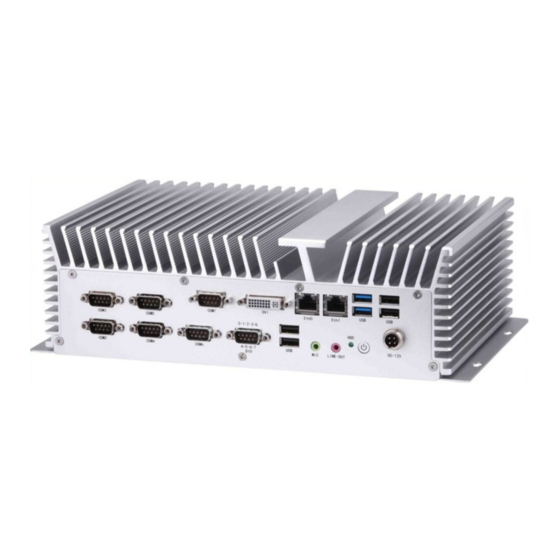
FEBC-3158 offers 1xDVI-I interface, 2xGiga Lan ports, 2xUSB3.0 ports, 4xUSB2.0 ports, Audio,6xCOM ports, 8 bit DIO port, 2xMini PCIe socket one is PCIex1 and USB signal,the other is mSATA; The FEBC-3158 supports 1x2.5 inch SATA HDD driver bay, 1xmSATA for storage ,DC 12V power input. 1.2 Features Key features 1、Aluminum chassis , Fanless design;... -
Page 10: Ethernet
User’s Manual 1.3.3 Ethernet Chipset: Intel® 82574L PCI Express Gigabit Ethernet controller Speed: 10/100/1000 Mbps Integrated Interface: 2 x RJ45 1.3.4 Audio Chipset: Realtek ALC662 HD Audio Codec integrated Interface: Line out , Mic phone jack 1.3.5 Power Consumption Input Voltage: DC 12V Power Consumption: TDP 12V/3.60A (Intel i5-2430M 2.4GHz with 4GB DDR3 memory) - Page 11 User’s Manual FEBC-3158-S001 Dimensions: Uint: mm Figure 1.1...
-
Page 12: Hardware Installation
User’s Manual Hardware Installation... -
Page 13: Introduction
2.2 Jumpers and connectors The FEBC-3158 Embedded Box Computer consists of an JHC SBC (Single Board Computer) board that is housed in an aluminum plate chassis. Your HDD and SDRAM, are all readily accessible by removing the aluminum bottom cover. Any maintenance or hardware upgrades can be easily completed after removing the bottom cover. -
Page 14: Setting Jumpers
2.2.1 Setting Jumpers You can configure your FEBC-3158 to match the needs of your application by setting the jumpers. A jumper is the simplest kind of electrical switch. It consists of two metal pins and a small metal clip (often protected by a plastic cover) that slides over the pins to connect them. -
Page 15: Jumper Location
2.3 Jumper Location The FEBC-3158 Embedded Box Computer has a number of jumpers inside the chassis that allows you to configure your system to suit your application. The table below lists the functions of the various jumpers. -
Page 16: Ps_On
User’s Manual 2.3.1 RTC1/SRTC1: Clear CMOS (2.0mm Pitch 1X2 Pin Header)CMOS clear jumper, CMOS clear operation will permanently reset old BIOS settings to factory defaults. Procedures of CMOS clear: a) Turn off the system and unplug the power cord from the power outlet. b) To clear the CMOS settings, use the jumper cap to close pins1 and 2 for about 3 seconds then reinstall the jumper clip back to pins open. -
Page 17: I/O Indication
User’s Manual 2.4 I/O indication Front view Rear view Figure 2.14... -
Page 18: Ethernet Connector (Lan)
RX-(10/100), BI_DB-(GHz) BI_DD+(GHz) BI_DD-(GHz) 2.4.2 Power Input Connector (DC-IN) The FEBC-3158 comes with a 4-pole DIN-jack that 12V external power input. Please refer to Table 2.2 for their pin assignments. Figure 2.16 4-pole DC DIN-Jack Table 2.2: Power Connector Pin Assignments... -
Page 19: Usb Connector
Figure 2.17 USB connector Table 2.3: USB Connector Signal name USB_P0 USB_P0+ The FEBC-3158 provides 2 USB3.0 ports by type A con-nectors. Please refer to Table 2.4 for their pin assignments. Figure 2.18: USB3.0 Connector Table 2.4: USB3.0 Port Pin Assignments Signal Name... -
Page 20: Com1/6 Connector
1.5A, please separate connectors into different Receptacle. 2.4.4 COM1/3 Connector The FEBC-3158 provides COM1 and COM3 are D-sub 9-pin connectors, Rear serial port, standard DB9 Male serial port is provided to make a direct connection to serial devices 2 3 4 6 7 8 9 Figure 2.19 COM1/3 Connector... -
Page 21: Sata_P1/Sata_P3: Sata Hard Disk Power-Out Connector
User’s Manual 2.4.6 COM6 Connector The FEBC-3158 provides COM6 is a D-sub 9-pin connectors, rear serial port, standard RS422/485 DB9 Male serial port is provided to make a direct connection to serial devices. Table 2.7: COM6 Serial Port Pin Assignments... -
Page 22: Sata1/Sata2
User’s Manual Note: Output current of the connector must not be above 1A. 2.4.9 SATA1/SATA2: (SATA 7P),SATA Connectors,Two SATA connectors are provided.Next-generation high-speed storage interface supporting up to 6 Gb/s transfer rates for optimal data access with up to 2 SATA 6Gb/s ports. 2.4.10 SATA3/SATA4: (SATA 7P),SATA Connectors,Two SATA connectors are provided,High-speed storage interface supporting up to 2 SATA 3Gb/s ports. -
Page 23: Installation
User’s Manual 2.5 Installation 2.5.1 HDD/SSD Installation Step 1.Unscrew the 4 screws on the bottom cover,and open the HDD cover. Step 2.Screw the HDD/SSD on the drive bay though 6 screws . Step 3.Place the drive bay into the bottom cover. Step 4.Screw 4 screws on the drive bay with the bottom cover. - Page 24 User’s Manual Figure 2.24 Figure 2.25...
-
Page 25: Installing Msata Flash Card (Mini Pcie/Sata )
User’s Manual Figure 2.26 2.5.2 Installing mSATA Flash Card (mini PCIe/SATA ) Step 1. Unscrew the 4 screws on the bottom cover, and open the HDD cover. Figure 2.27... - Page 26 User’s Manual Step 2. Put mSATA Flash Card on this place as shown in the picture. Figure 2.28 Step 3. Hold the Module with its notch aligned with the socket of the board and insert it at a 30 degree angle into the socket as shown in the picture.
- Page 27 User’s Manual Step 4. Screw one screws to the holder as shown in the picture. Figure 2.30 Step 5.Close the HDD cover ,screw the 4 screws on the bottom cover Figure 2.31...
-
Page 28: Bios Setup
User’s Manual BIOS Setup... -
Page 29: Bios Illustration
User’s Manual 3.1 BIOS Illustration The BIOS is a program located on a Flash Memory on the motherboard. This program is a bridge between motherboard and operating system. When you start the computer,the BIOS program will gain control. The BIOS first operates an auto-diagnostic test called POST (power on self test) for all the necessary hardware, it detects the entire hardware device and configures the parameters of the hardware synchronization.Only when these tasks are completed done it gives up control of the computer to operating system (OS). -
Page 30: Function Keys
User’s Manual 3.4 Function Keys In the above BIOS Setup main menu of, you can see several options. We will explain these options step by step in the following pages of this chapter, but let us first see a short description of the function keys you may use here: ... - Page 31 User’s Manual Month: 01 to 12 Date: 01 to 31 Year: 1998 to 2099 System Time Set the time. Please use [Tab] to switch between time elements, the time format is: Hour : 0 to 23 Minute : 0 to 59 Second : 0 to 59 3.8 Advanced Setting Figure 3.2...
- Page 32 User’s Manual PCI Latency Timer: [32 PCI Bus Clocks] [64 PCI Bus Clocks] [96 PCI Bus Clocks] [128 PCI Bus Clocks] [160 PCI Bus Clocks] [192 PCI Bus Clocks] [224 PCI Bus Clocks] [248 PCI Bus Clocks] VGA Palette snoop: [Disabled] [Enabled] PERR# Generation:...
- Page 33 User’s Manual [Enabled] Link Training Retry [5] Link Training Timeout(us) 100 Unpopulated Links [Keep Link ON] ACPI Settings PEnable ACPI Auto Configuration: [Disabled] [Enabled] Enable Hibernation: [Enabled] [Disabled] ACPI Sleep State: [Both S1 and S3 available for OS to choose from] [Suspend Disabled] [S1 only(CPU Stop Clock)] [S3 only(CPU Stop RAM)]...
- Page 34 User’s Manual Intel Virtualization Technology: [Enabled] [Disabled] Hardware Prefetcher: [Enabled] [Disabled] Adjacent Cache Line Prefetch: [Enabled] [Disabled] SATA Configuration SATA Controller(S): [Enabled] [Disabled] SATA Mode Selection: [IDE] [AHCI] SATA Test Mode: [Disabled] [Enabled] IDE Legacy / Native Mode Selection [Native] [Lrgacy] Serial ATA Port 0...
- Page 35 User’s Manual [Disabled]. PCH-FW Configuration ME FW Version 8.0.13.1502 ME Firmware Mode Normal Mode ME Firmware Type Full Sku Firmware ME Firmware SKU 1.5MB MEBx Type [None] MDES BIOS Status Code [Disabled] Firmware Update Configuration ME FW Image Re-Flash [Disabled] [Enabled].
- Page 36 User’s Manual [Enabled] USB Configure [Enabled] [Disabled] PET Progure [Enabled] [Disabled] AMT CIRA Timeout WatchDog [Disabled] [Enabled] OS Timer BIOS Timer USB Configuration PUSB Configuration USB Devices: 1 keyboard, 2 Hubs Legacy USB Support: [Enabled] [Disabled] USB3.0 Support: [Enabled] [Disabled] XHCI Hand-off: [Disabled]...
- Page 37 User’s Manual Serial Port 3 Configuration Serial Port 4 Configuration Serial Port 5 Configuration Serial Port 6 Configuration Hardware Monitor PPC Health Status System temperature : +36 C CPU temperature : +59 CPU Fan Speed : 6250 RPM VCORE : +1.008V +12V : +11.392 V +3.3V : +3.424 V +1.5V : +1.520 V...
-
Page 38: Advanced Setting
User’s Manual [Enabled] Long duration power limit 0 Long duration maintained 0 Short duration power limit 0 ACPI T State [Disabled] 3.9 Chipset Setting Figure 3.3 System Agent (SA) Configuration >System Agent (SA) Bridge Name Sandybridge System Agent RC Version 1.6.0.0 VT-d Capability Supported VT-d [Enabled]... - Page 39 User’s Manual Enable NB CRID [Disabled] [Enabled] BDAT ACPI Table Support >Graphics Configuration IGFX VBIOS Version 2158 IGFX Frequency 650 MHz Primary Display [Auto] [IGFX] [PEG] [PCI] Internal Graphics [Auto] [Disabled] [Enabled] GTT Size [2MB] [1MB] Aperture Size [256MB] [128MB] [512MB] DVMT Pre-allocated [64M]...
- Page 40 User’s Manual >LCD Control: Primary IGFX Boot Display [VBIOS Default] [VGA] [DVI] [LVDS] LCD Panel Type [1280 X 1024 24bit 2ch] [640 X 480 18bit 1ch] [800 X 480 18bit 1ch] [800 X 600 18bit 1ch] [800 X 600 24bit 1ch] [1024 X 768 18bit 1ch] [1024 X 768 24bit 1ch] [1280 X 800 18bit 1ch]...
- Page 41 User’s Manual Active LFP [Int-LVDS] [No LVDS] [SDVO LVDS] [eDP Port-A] [eDP Port-D] Panel Color Depth [24 Bit] [18 Bit] >DMI Configuration >NB PCIe Configuration PEG0 [Not Present] PEG0 – Gen X [Auto] [Gen1] [Gen2] [Gen3] PEG0 – ASPM [Auto] [Disabled] [ASPM Los] [ASPM L1]...
- Page 42 User’s Manual Row Precharge (tRPmin) 9 Active to Precharge (tRPmin) 24 >GT-Power Management Control GT Info GT2 (0X126) RC6 (Render Standby) [Enabled] [Disabled] RC6 +(Deep RC6) [Enabled] [Disabled] GT Overclocking Support [Disabled] [Enabled] PCH-IO Configuration Intel PCH RC Version 1.6.0.0 Intel PCH SKU Name HM77 Intel PCH Rev ID 04/C1...
- Page 43 User’s Manual HS Port #1 Switchable [Enabled] [Disabled] HS Port #2 Switchable [Enabled] [Disabled] HS Port #3 Switchable [Enabled] [Disabled] HS Port #4 Switchable [Enabled] [Disabled] Xhci Streams EHCT1 [Enabled] [Disabled] EHCT2 [Enabled] [Disabled] USB Ports Per-Port Disable Control [Disabled] [Enabled] ...
- Page 44 User’s Manual [Enabled] [Disabled] PCH LAN Controller [Disabled] [Enabled] Board Capability [SUS_PWR_DN_ACK] [Deepsx] Display Logic [Enabled] [Disabled] CLKRUN# Logic [Enabled] [Disabled] SB CRID [Disabled] [Enabled] High Precision Event Timer Configuration High Precision Timer [Enabled] [Disabled] SLP_S4 Assertion Width [4-5 Seconds] [1-2 Seconds] [2-3 Seconds] [3-4 Seconds]...
- Page 45 User’s Manual 3.10 Boot Settings Figure 3.4 Setup Prompt Timeout [1] Bootup Numlock State [On] [off] Quiet Boot [Disabled] [Enabled] Fast Boot [Disabled] [Enabled] CSM16 Module Verison 07.69 Gatea20 Active [Upon Request] [Always] Option ROM Messages [Force BIOS] [Keep Current] IN19 Trap Response...
- Page 46 User’s Manual [Immediate] [Postponed] Boot Option Priorities CSM parameters Launch CSM [Enabled] [Disabled] Boot option Filter [UEFI and Legacy] [Legacy only] [UEFI only] Launch PXE OpROM policy [Do not launch] [UEFI only] [Legacy only] Launch Storage OpROM policy [Legacy only] [UEFI only] [Do not launch] Launch Video OpROM policy...
-
Page 47: Security Settings
User’s Manual 3.11 Security Settings Figure 3.5 Administrator Password User Password Type the password w all previously typed CMOS passwords. You will be requested to confirm the password. abandon password entry operation. A confirmation message will be shown on the screen as to whether the password will be disabled. You will have direct access to BIOS setup without typing any password after system reboot once the password is disabled. -
Page 48: Save & Exit Menu
User’s Manual Once the password feature is used, you will be requested to type the password each time you enter BIOS setup. This will prevent unauthorized persons from changing your system configurations. Also, the feature is capable of requesting users to enter the password prior to system boot to control unauthorized access to your computer. - Page 49 User’s Manual Discard Changes and Reset Reset Without Saving Reset without saving? [Yes] [No] Save Changes Save Setup Values Save configuration? [Yes] [No] Discard Changes Load Previous Values Load Previous Values? [Yes] [No] Restore Defaults Load Optimized Defaults Load optimized Defaults? [Yes] [No] Save user Defaults...
-
Page 50: Driver Installation
User’s Manual Installation Driver... -
Page 51: Follow The Sequence Below To Install The Drivers
Step 9– Install Infineon TPM Driver and Tool Please read instructions below for further detailed installations. 4.2 Installation: Insert the FEBC-3158 CD-ROM into the CD-ROM drive. And install the drivers from Step 1 to Step 4 in order. Step 1 – Install Chipset Driver 1)Click on the Step 1 - Intel Chipset Software Installation Utility folder and double click on the infinst_autol.exe... - Page 52 User’s Manual 1) Click on the Step 5 - Realtek HD Audio Codec folder and select the OS folder your system is 2)Double click on Setup.exe file located in each OS folder 3)Follow the instructions that the window shows 4)The system will help you install the driver automatically Step 6 –Intel USB 3.0 Drivers (For Windows 7 Only) 1) Click on the Step 6 -Install“Intel USB 3.0 Driver”...
-
Page 53: System Resource
User’s Manual SYSTEM RESOURCE... -
Page 54: Wdt Function
User’s Manual 5.1 WDT Function WDT Set Example #include <stdio.h> #include "stdafx.h" #include <windows.h> typedef int(_stdcall *IpMyin)(int); typedef int(_stdcall *IpMyout)(int,int); void set_watchdog(int time) HINSTANCE hDll; IpMyin Myin; IpMyout Myout; hDll = LoadLibrary(_T("inpout32.dll")); if (hDll != NULL) Myin = (IpMyin)GetProcAddress(hDll, "Inp32"); Myout = (IpMyout)GetProcAddress(hDll, "Out32");... - Page 55 User’s Manual Myout(0x4e,0xf6); Myout(0x4f,time); //set counts Myout(0x4e,0xaa); //lock FreeLibrary(hDll); //释放此 DLL void disable_watchdog() set_watchdog(0); int _tmain(int argc, _TCHAR* argv[]) set_watchdog(5); getchar(); return 0;...
-
Page 56: Digital Io Function
User’s Manual 5.2 Digital IO Function Sample Code #include "stdafx.h" #include "L706_GPIO_TEST.h" #include "L706_GPIO_TESTDlg.h" #include "WinIo.h" #ifdef _DEBUG #define new DEBUG_NEW #undef THIS_FILE static char THIS_FILE[] = __FILE__; #endif ///////////////////////////////////////////////////////////////////////////// // CAboutDlg dialog used for App About class CAboutDlg : public CDialog public: CAboutDlg();... - Page 57 User’s Manual CDialog::DoDataExchange(pDX); //{{AFX_DATA_MAP(CAboutDlg) //}}AFX_DATA_MAP BEGIN_MESSAGE_MAP(CAboutDlg, CDialog) //{{AFX_MSG_MAP(CAboutDlg) // No message handlers //}}AFX_MSG_MAP END_MESSAGE_MAP() ///////////////////////////////////////////////////////////////////////////// // CL706_GPIO_TESTDlg dialog CL706_GPIO_TESTDlg::CL706_GPIO_TESTDlg(CWnd* pParent /*=NULL*/) : CDialog(CL706_GPIO_TESTDlg::IDD, pParent) //{{AFX_DATA_INIT(CL706_GPIO_TESTDlg) // NOTE: the ClassWizard will add member initialization here //}}AFX_DATA_INIT // Note that LoadIcon does not require a subsequent DestroyIcon in Win32 m_hIcon = AfxGetApp()->LoadIcon(IDR_MAINFRAME);...
- Page 58 User’s Manual ///////////////////////////////////////////////////////////////////////////// // CL706_GPIO_TESTDlg message handlers BOOL CL706_GPIO_TESTDlg::OnInitDialog() CDialog::OnInitDialog(); // Add "About..." menu item to system menu. // IDM_ABOUTBOX must be in the system command range. ASSERT((IDM_ABOUTBOX & 0xFFF0) == IDM_ABOUTBOX); ASSERT(IDM_ABOUTBOX < 0xF000); CMenu* pSysMenu = GetSystemMenu(FALSE); if (pSysMenu != NULL) CString strAboutMenu;...
- Page 59 User’s Manual m_ButtonLED4.SetLED(pWndLedBtn4,ID_LED_GREEN,ID_SHAPE_ROUND,500); m_ButtonLED4.SwitchOn(); m_ButtonLED4.LedOff(); InitializeWinIo(); CWnd *pWndLedBtn5 = (CWnd *)GetDlgItem(IDC_BTN_LED5); m_ButtonLED5.SetLED(pWndLedBtn5,ID_LED_GREEN,ID_SHAPE_ROUND,500); m_ButtonLED5.SwitchOn(); m_ButtonLED5.LedOff(); CWnd *pWndLedBtn6 = (CWnd *)GetDlgItem(IDC_BTN_LED6); m_ButtonLED6.SetLED(pWndLedBtn6,ID_LED_GREEN,ID_SHAPE_ROUND,500); m_ButtonLED6.SwitchOn(); m_ButtonLED6.LedOff(); InitializeWinIo(); CWnd *pWndLedBtn7 = (CWnd *)GetDlgItem(IDC_BTN_LED7); m_ButtonLED7.SetLED(pWndLedBtn7,ID_LED_GREEN,ID_SHAPE_ROUND,500); m_ButtonLED7.SwitchOn(); m_ButtonLED7.LedOff(); CWnd *pWndLedBtn8 = (CWnd *)GetDlgItem(IDC_BTN_LED8); m_ButtonLED8.SetLED(pWndLedBtn8,ID_LED_GREEN,ID_SHAPE_ROUND,500); m_ButtonLED8.SwitchOn(); m_ButtonLED8.LedOff(); InitializeWinIo(); SetTimer(1,200, 0);...
- Page 60 User’s Manual void CL706_GPIO_TESTDlg::OnPaint() if (IsIconic()) CPaintDC dc(this); // device context for painting SendMessage(WM_ICONERASEBKGND, (WPARAM) dc.GetSafeHdc(), 0); // Center icon in client rectangle int cxIcon = GetSystemMetrics(SM_CXICON); int cyIcon = GetSystemMetrics(SM_CYICON); CRect rect; GetClientRect(&rect); int x = (rect.Width() - cxIcon + 1) / 2; int y = (rect.Height() - cyIcon + 1) / 2;...
- Page 61 User’s Manual SetPortVal(0x544, 0x00, 1); //GPIO68 69 70 71 SetPortVal(0x545, 0x00, 1); //GPIO75 SetPortVal(0x507, 0xA6, 1); //GPIO27 SetPortVal(0x537, 0x09, 1); //GPIO57 58 unsigned char B0 = ((CButton*) GetDlgItem(IDC_CHECK1))->GetCheck(); unsigned char B1 = ((CButton*) GetDlgItem(IDC_CHECK2))->GetCheck(); unsigned char B2 = ((CButton*) GetDlgItem(IDC_CHECK3))->GetCheck(); unsigned char B3 = ((CButton*) GetDlgItem(IDC_CHECK4))->GetCheck();...
- Page 62 User’s Manual unsigned char GPIO6 = ( (B4 << 3) ) & 0xFF; SetPortVal(0x50F, GPIO6, 1); //GPIO27 if(B5) if(B6) GPIO6 = 0xFF; else GPIO6 = 0xFB; else if(B6) GPIO6 = 0xFD; else GPIO6 = 0xF9; SetPortVal(0x53B, GPIO6, 1); //GPIO57 58 GPIO6 = ( (B7 <<...
- Page 63 User’s Manual GetPortVal(0x548, &dwPortVal, 1); if(dwPortVal>>7&0x01) m_ButtonLED4.LedOn(); else m_ButtonLED4.LedOff(); if(dwPortVal>>6&0x01) m_ButtonLED3.LedOn(); else m_ButtonLED3.LedOff(); if(dwPortVal>>5&0x01) m_ButtonLED2.LedOn(); else m_ButtonLED2.LedOff(); if(dwPortVal>>4&0x01) m_ButtonLED1.LedOn(); else m_ButtonLED1.LedOff(); void CL706_GPIO_TESTDlg::Gpio6_In_detect() DWORD dwPortVal=0; GetPortVal(0x549, &dwPortVal, 1); //GPIO75 if(dwPortVal>>3&0x01) m_ButtonLED8.LedOn(); else m_ButtonLED8.LedOff(); GetPortVal(0x53B, &dwPortVal, 1); //GPIO58 if(dwPortVal>>2&0x01) m_ButtonLED7.LedOn(); else m_ButtonLED7.LedOff();...
- Page 64 User’s Manual m_ButtonLED5.LedOff();...
Need help?
Do you have a question about the FEBC-3158 and is the answer not in the manual?
Questions and answers