Table of Contents
Advertisement
Quick Links
Advertisement
Table of Contents

Related Manuals for JHCTech SIGM-3250 Series


Summary of Contents for JHCTech SIGM-3250 Series
- Page 1 用户手册 User’s Manual SIGM-3250 Ver.: A0.1 Date:2020-05-09...
- Page 2 User’s Manual Version Note Ver. Note Date Writer A0.1 first publish 20200509 Echo Guo...
- Page 3 User’s Manual Copyright The documentation and the software included with this product are copy- righted 2020 by Shenzhen JHC Technology Development Co.,Ltd. All rights are reserved. Shenzhen JHC Technology Development Co.,Ltd. reserves the right to make improvements in the products described in this manual at any time without notice.
- Page 4 User’s Manual Product Warranty (2 years) JHC warrants to you, the original purchaser, that each of its products will be free from defects in materials and workmanship for 2 years from the date of purchase. This warranty does not apply to any products which have been repaired or altered by persons other than repair personnel authorized by JHC, or which have been subject to misuse, abuse, accident or improper installation.
- Page 5 Technical Support and Assistance Step 1. Visit the JHC web site at www.jhctech.com.cn where you can find the latest information about the product. Step 2. Contact your distributor, sales representative, or JHC’s customer service center for technical support if you need additional assistance.
-
Page 6: Table Of Contents
User’s Manual CONTENTS General Information ................... 4 1.1 Introduction ..........................5 1.2 Features ........................... 5 1.3 Specifications ........................... 6 1.3.1 General ............................6 1.3.2 Display ............................6 1.3.3 Ethernet ............................7 1.3.4 Audio ............................. 7 1.3.5 Power Consumption ........................7 1.4 Environmental Specifications .................... - Page 7 User’s Manual 2.3.6 Smart Display ..........................20 2.3.7 COM1/2 ............................20 2.3.8 Option CAN /AUDIO ........................21 2.3.9 DIO .............................. 21 2.3.10 Remote Switch .......................... 22 2.3.11 Mini PCIe1/2 ..........................22 2.3.12 Mini PCIe3 ..........................23 2.3.13 mSATA ............................25 2.3.14 LED ............................
- Page 8 User’s Manual 4.1 Follow the sequence below to install the drivers: ..............59 4.2 Installation: ..........................59 4.3 CPU TEMP LED driver....................... 60 4.4 Utility Software Reference ...................... 61 SYSTEM RESOURCE ..................62 5.1 WDT and GPIO ........................63...
-
Page 9: General Information
User’s Manual General Information... -
Page 10: Introduction
User’s Manual 1.1 Introduction SIGM-3250 is a fan-less reinforced on-board computer, and the mainboard and sub-board are designed with an all-in-one architecture without connection. The SIGM-3250 is equipped with equipped with Intel® Skylake/kabylake-U Core I3/I5/I7 CPU, support for dual channel DDR4 (on-board 4 /8GB +SODIMM), up to 16GB, and the 9th generation Intel®... -
Page 11: Specifications
User’s Manual Smart Display Line out mSATA 2.5” SATA bay Power input DC 48/72/110V DC 48/72/110V DC 9~36V, ITPS DC 9~36V, ITPS Table 1.1: Features 1.3 Specifications 1.3.1 General CPU: Intel® Skylake/Kabylake-U Core I3/I5/I7 CPU System Memory: Dual channel (on-board 4/8GB +SODIMM) DDR4, 2133MHz, up to 16GB Watchdog Timer: 255-level interval timer, setup by software USB:... -
Page 12: Ethernet
User’s Manual 1.3.3 Ethernet Chipset: 6*Intel I210AT 6*Intel I210AT PCIe Gig. Ethernet, 4 with POE, 802.3af (15.4w) Speed: 10/100/1000 Mbps Interface: 2*Gig-LAN (M12 X-coded), 4*Gig-LAN, with POE 802.3af 15.4W (M12 X-coded) 1.3.4 Audio Chipset: Realtek ALC662VD Interface:1* Audio out,1*Mic,3.5mm phone jack 1.3.5 Power Consumption Input Voltage: DC 9-36V,with ITPS power management (S001/S003) -
Page 13: Mechanical Specifications
User’s Manual 1.5 Mechanical Specifications The SIGM-3250 is a fan-less reinforced on-board computer, consists of a mainboard (STX-I907), a sub-card (ECB-9070), power strip (OFX-100). STX-I907 Front Picture 1.1: STX-I907 Front STX-I907 Rear Picture 1.2: STX-I907 Rear... - Page 14 User’s Manual ECB-9070 Front Picture 1.3: ECB-9070 OFX-100 Front Picture 1.3: OFX-100 SIGM-3250 Front Panel Picture 1.4: SIGM-3250 Front Panel...
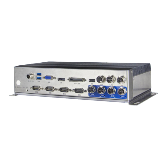
- Page 15 User’s Manual SIGM-3250 Rear Panel Picture 1.5: SIGM-3250 Rear Panel SIGM-3250 Dimension: Unit: mm Picture 1.6 SIGM-3250 Dimension...
-
Page 16: Hardware Installation
User’s Manual Hardware Installation... -
Page 17: Introduction
User’s Manual 2.1 Introduction The following sections show the internal switch settings and the external connectors and pin assignments for applications. 2.2 Switches The SIGM-3250 box computer has a number of switches inside the chassis that allows you to configure your system to suit your application. -
Page 18: At/Atx Power On Mode Selection
User’s Manual 2.2.2 AT/ATX Power on mode selection Picture 2.2: AT/ATX The SIGM-3250 provides an AT/ATX SW, which users can set Power-on mode by it. When you dial it at AT, it means power on by AC Power; When you dial it at ATX, it means power on by Power button. 2.2.3 ACC/Family Mode selector switch Picture 2.3: ACC/Family The SIGM-3250 provides ACC/Family switch, and users can set the on-off mode of the machine by pushing... -
Page 19: I/O/Button/Led Indication
User’s Manual 2.3 I/O/Button/LED Indication SIGM-3250 Front: Picture 2.4: SIGM-3250 Front The front panel contains the I/O interface: 1*DC-in Power: M12 A-Code 5-pole terminal DC9~36V(S001/S003) 1*DC-in Power: M12 A-Code 4-pole terminal DC 48/72/110V(T001/T003) 2*USB3.0 Type A, 1*USB2.0 Type A, 2*USB2.0 M12 A-Code ... -
Page 20: Ethernet Connector (Poe)
User’s Manual The rear panel contains the I/O interface: Power button HDD LED, CPU LEDs,LAN LEDs AT/ATX SW, Clear CMOS SW, ACC/Family SW 2*SIM,1*2.5”SATA bay 1*Line-out,1*Mic 1*Remote SW 4*Antenna 2.3.1 Ethernet Connector (POE) The SIGM-3250 is equipped with 6*Intel®... -
Page 21: Power Input (Dc-In)
User’s Manual 2.3.2 Power input (DC-IN) SIGM-3250-S001/S003 power input adopts DC 9~36V, ITPS, SIGM-3250-T001/T003 power input adopts railway standard power DC 48/72/110V. The DC 9~36V equipped 5-Pin M12 A-code power socket can support up to 60W power. This is a low power solution that uses a 12V AC to DC adapter for input DC power to the socket. -
Page 22: Usb
User’s Manual Table 2.1: DC 48/72/110V M12 A-Code Connector Pin Assignments Signal VIN+ VIN+ VIN- VIN- 2.3.3 USB SIGM-3250 supports 2*USB3.0 (Type A); 1*USB2.0 (Type A); 1*USB2.0 (8-pin M12 A-code), These USB connectors support plug and play and hot plug capabilities. Interface comply with the USB UHCI version 3.0 and 2.0 protocols and can be disabled through the system BIOS Settings. -
Page 23: Vga
User’s Manual Picture 2.10: USB2.0 Type A Table 2.5: USB3.0 Type A Connector Pin Assignments Signal USB_VCC USB_D- USB_D+ USB_GND Picture 2.11: USB2.0 M12 A-Code Table 2.6: USB2.0 M12 A-Code Connector Pin Assignments Signal VBUS VBUS 2.3.4 VGA SIGM-3250 provides a standard VGA interface that supports up to a maximum resolution of 1920* 1200@60Hz. - Page 24 User’s Manual Picture 2.12: VGA Table 2.6: VGA Connector Pin Assignments Signal Signal GREEN BLUE 2.3.5 DP The SIGM-3250 provides a high resolution DP interface that supports up to a maximum resolution of 4096* 2160@60Hz. Detailed pin assignment is described in table 2.7. Picture 2.12: DP Table 2.7: DP Connector Pin Assignments Signal...
-
Page 25: Smart Display
User’s Manual 2.3.6 Smart Display The SIGM-3250 provides a Smart Display interface through a SCSI socket, supporting up to a maximum resolution of 1920* 1200@60 Hz. Detailed pin assignment is described in table 2.8. Picture 2.13: Smart Display Table 2.8: Smart Display Connector Pin Assignments Signal Signal Signal... -
Page 26: Option Can /Audio
User’s Manual 2.3.8 Option CAN /AUDIO SIGM-3250 provides 2* optional CAN/AUDIO port through 1* d-sub 9-pin connector. Table 2.10 provides detailed descriptions of pin assignments. (When selecting AUDIO, the signal definition can be customized according to the line.) Picture 2.15: optional CAN/AUDIO Table 2.10: Option CAN Connector Pin Assignments Signal Signal... -
Page 27: Remote Switch
User’s Manual 2.3.10 Remote Switch The remote switch signal interface for switching machine is a 2-pin terminal at the end of the sub-card coastline, pin definition is shown in table 2.12. Picture 2.17: Remote Switch Table 2.12: Remote Switch Connector Pin Assignments Signal PWR_BTN 2.3.11 Mini PCIe1/2... -
Page 28: Mini Pcie3
User’s Manual Table 2.13: Mini PCIe 1/2 Connector Pin Assignments Signal Signal PCIE_WAKE_N +V3.3_MINICARD1 +V1.5 +V3.3_MINICARD1 +VUIM_PWR UIM_DATA CLK_MINI1_PCIE- UIM_CLK CLK_MINI1_PCIE+ UIM_RESET +VUIM_VPP WIFI1_DISABLE# PLTRST# PCIE_MINI_RX1- +V3.3_MINICARD1 PCIE_MINI_RX1+ +V1.5 SMB_SCL_RSM PCIE_MINI_TX1- SMB_SDA_RSM PCIE_MINI_TX1+ USB_N7 USB_N9 +V3.3_MINICARD2 +V3.3_MINICARD2 SIM1-DET +V1.5 +V3.3_MINICARD1 2.3.12 Mini PCIe3 The SIGM-3250 mainboard (STX-I907) also provides 1*Mini PCIe pin spacing 5.2mm interface (Mini PCIe2) with USB signal. - Page 29 User’s Manual Picture 2.18: Mini PCIe3 Table 2.14: Mini PCIe2 Connector Pin Assignments Signal Signal PCIE_WAKE_N +V3.3_MINICARD3 +V1.5_MINICARD3 +V3.3_MINICARD3 +VUM_PWR3 UIM_DATA3 CLK_MINI3_PCIE- UIM_CLK3 CLK_MINI3_PCIE+ UIM_RESET3 +VUIM_VPP3 WIFI3_DISABLE# PLTRST_N PCIE_MINI3_RX5- +V3.3_MINICARD3 PCIE_MINI3_RX5+ +V1.5_MINICARD3 SMB_SCL_RSM PCIE_MINI3_TX5- SMB_SDA _RSM PCIE_MINI3_TX5+ USB_HUB_P- USB_HUB_P+...
-
Page 30: Msata
User’s Manual +V3.3_MINICARD3 +V3.3_MINICARD3 +V1.5_MINICARD3 +V3.3_MINICARD3 2.3.13 mSATA The SIGM-3250 mainboard (STX-I907) provides a standard mSATA interface with SATA+USB signal. Picture 2.19: mSATA 2.3.14 LED The SIGM-3250 panel has one power indicator, one hard disk indicator, three network connection status indicators, and three CPU operating temperature indicators. -
Page 31: Installation
User’s Manual 2.4 Installation 2.4.1 HDD/SSD installation Step 1: unscrew the 2 screws on the HDD/SSD bracket of the rear panel. Step 2: remove the HDD/SSD stent. Step 3: load the HDD/SSD into the bracket and tighten the 4 screws on the left and right sides to fix the HDD/SSD. - Page 32 User’s Manual Picture 2.22: HDD/SSD installation(3) Picture 2.23: HDD/SSD installation(4)...
-
Page 33: Sim1/Sim2 Installation
User’s Manual 2.4.2 SIM1/SIM2 installation Step 1: unscrew the 2 screws of the rear panel SIM1/SIM2 and remove the SIM1/SIM2 baffle Step 2: push the SIM card into the corresponding SIM card slot Step 3: fix the SIM1/SIM2 baffle with 2 screws Picture 2.24: SIM1/SIM2 installation(1)... -
Page 34: Msata Installation
User’s Manual 2.4.3 mSATA installation Step 1: unscrew the 2 screws on the HDD/SSD bracket in the back panel, and remove the HDD/SSD bracket Step 2: unscrew the 5 screws on the bottom cover and remove the mounting bracket and bottom cover Step 2: unscrew 12 screws on left and right sides and back panel Step 3: remove the back panel cover, insert the mSATA module, and screw Step 5: complete the installation of the panel cover and bottom cover with the reverse step... - Page 35 User’s Manual Picture 2.28: mSATA installation(3) Picture 2.29: mSATA installation(4)...
-
Page 36: Mini Pcie Installation
User’s Manual 2.4.4 Mini PCIe installation Step 1: it is consistent with mSATA module installation steps. For details, please refer to "2.4.3 mSATA installation". Picture 2.30: Mini PCIe installation(1)... -
Page 37: Bios Setup
User’s Manual BIOS Setup... -
Page 38: Bios Description
User’s Manual 3.1 BIOS Description BIOS is the communication bridge between hardware and software. How to correctly set the BIOS parameters is crucial for the system to work stably and whether the system works at its best. This chapter describes how to change the system settings through the BIOS settings. Note: For the purpose of better product maintenance, the manufacture reserves the right to change the BIOS items presented in this manual. -
Page 39: Bios Parameter Settings
User’s Manual 3.2 BIOS parameter settings When you start the Setup Utility, the main menu appears. The main menu of the Setup Utility displays a list of the options that are available. A highlight indicates which option is currently selected. Use the cursor arrow keys to move the highlight to other options. -
Page 40: Bios Navigation Keys
User’s Manual 3.2.1 BIOS Navigation Keys Enter the SETUP settings interface, The BIOS navigation keys are listed below: Table 3.1: The BIOS navigation keys FUNCTION Exit the current menu ↑↓→← Scrolls through the items on a menu Change Opt. Enter Select General Help Previous Values... - Page 41 User’s Manual...
-
Page 42: Advanced Menu
User’s Manual BIOS Vendor (American Megatrends) This item shows the information of the BIOS vendor. Core Version (5.13) This item shows the information of the Core Version. Project Version (V909S 0.01 X64) This item shows the information of the motherboard Version. Build Date and Time This item shows the information of the BIOS build date and time Processor Information... - Page 43 User’s Manual ▶ CPU Configuration The configuration of the central processor, enter this sub-menu, there will be detailed details of the CPU, as well as various settings of the CPU.
- Page 44 User’s Manual ▶ Power & Performance This item in the menu shows how to set the Power Management Control of CPU and GT.
- Page 45 User’s Manual ▶ Trusted Computing Trusted computing, enter this sub-menu, there will be the setting of the encryption security module (the motherboard will install the encryption module hardware will take effect)
- Page 46 User’s Manual ▶ ACPI Settings Advanced configuration and power management interface settings, enter this submenu, there will be ACPI related settings. ACPI Sleep State (S3 (Suspend to RAM)) This item allows user to enter the ACPI S3 (Suspend to RAM) Sleep State (default).
- Page 47 User’s Manual Press <Esc> to return to the Advanced Menu page. ▶ SIO Configuration setting Super IO Configuration settings, enter this sub-menu, there will be set COM working mode or disabled the Serial port function. ▶ Hardware Monitor Hardware monitoring, enter this sub-menu, there will be CPU temperature, System temperature, status display of each common working voltage.
- Page 48 User’s Manual ▶ CSM Configuration CSM (Compatibility Support Module) configuration, enter this sub-menu, there will be various settings to support UEFI startup and non-UEFI startup. If you need to start the traditional MBR device, you need to enable CSM. Turning off the CSM turns it into a pure UEFI boot.
- Page 49 User’s Manual CSM Support Compatibility Support Module, which is a compatibility module, is a special module of UEFI and provides compatibility support for system that do not support UEFI. GateA20 Active This item indicates whether to disable GA20 through the BIOS server or keep the activation status all the time.
-
Page 50: Chipset Menu
User’s Manual Legacy USB Support This item is used to set the USB interface support. If you need to support USB devices under DOS, such as U disk, USB keyboard, etc., set this item to [Enabled]. Otherwise, select [Disabled]. USB Mass Storage Driver Support USB mass storage device support switch. - Page 51 User’s Manual ▶ Memory Configuration Memory configuration, enter this submenu, there will be detailed memory information.
- Page 52 User’s Manual ▶ Memory Thermal Configuration Memory Power and Thermal Throttling This item contains the configuration of the Memory Power and Thermal Throttling. Memory Thermal Management This item sets the Memory Thermal Management on(Enabled) or off(Disabled). ▶ Memory Training Algorithms This item shows the information of the Memory Training Algorithms.
- Page 53 User’s Manual ▶ Graphics Configuration Image processing configuration, enter this sub-menu, there will be CPU-integrated graphics related settings.
- Page 54 User’s Manual ▶ External Gfx Card Primary Display Configuration...
- Page 55 User’s Manual ▶ LCD Control Primary IGFX Boot Display This item sets IGFX main display device on POST stage, not affected by external graphics card, options are HDMI, LFP, EFP3, DP, EFP4. It defaults by VBIOS. LCD Panel Type This item sets resolution of the motherboard LVDS screen. It defaults by VBIOS.
- Page 56 User’s Manual VT-d This item sets the VT-d technology to open or close. The default is Enabled. PCH-IO Configuration (South Bridge Configuration) ▶ PCI Express Configuration ▶ SATA And RST Configuration SATA hard disk and fast storage configuration, enter this sub-menu, there will be related settings of the hard disk.
- Page 57 User’s Manual ▶ USB Configuration...
-
Page 58: Security Menu
User’s Manual 3.2.5 Security menu Administrator Password This item sets the information of the administrator password. User Password This item sets the information of the normal user password. ▶ Secure Boot... -
Page 59: Boot Menu
User’s Manual 3.2.6 Boot menu Setup Prompt Timeout Setup prompts for waiting time. This option is to set the time to wait for the Del key to enter the BIOS setup... -
Page 60: Save & Exit Menu
User’s Manual after booting. Bootup NumLock State Set the state of the small numeric keypad at startup. Quiet Boot Switch full screen logo control Fast Boot Turn the quick start function on or off. When set to "Enabled", the system will skip some detection items and reduce the startup time. - Page 61 User’s Manual Save changes and Exit; This item enables you to save the changes that you have made and exit. Discard Changes and Exit; This item enables you to discard the changes that you have made and exit. Save Changes and Reset; This item enables you to save the changes that you have made and reset.
-
Page 62: Updating The Bios
User’s Manual 3.3 Updating the BIOS The BIOS (Basic Input and Output System) Setup Utility displays the system’s configuration status and provides you with options to set system parameters. The parameters are stored in battery-backed-up CMOS RAM that saves this information when the power is turned off. When the system is turned back on, the system is configured with the values you stored in CMOS. -
Page 63: Driver Installation
User’s Manual Driver Installation... -
Page 64: Follow The Sequence Below To Install The Drivers
User’s Manual The ECN-A K92618 comes with a CD-ROM that contains all drivers and utilities that meet your needs. 4.1 Follow the sequence below to install the drivers: Figure 5.1 win7 drivers Figure 5.1 win7 drivers Figure 5.2 win10 drivers Step 1 –... -
Page 65: Cpu Temp Led Driver
User’s Manual Step 1 – Install Graphic Driver 1. Double click on the Display folder and double click on the Setup.exe 2. Follow the instructions that the window shows 3. The system will help you install the driver automatically Step 2 – Install Audio Driver 1. -
Page 66: Utility Software Reference
User’s Manual Figure 5.3 4.4 Utility Software Reference All the utility software available from this page is Windows compliant. They are provided only for the convenience of the customer. The following software is furnished under license and may only be used or copied in accordance with the terms of the license. -
Page 67: System Resource
User’s Manual SYSTEM RESOURCE... -
Page 68: Wdt And Gpio
User’s Manual 5.1 WDT and GPIO /* ====================================================================== * void jhctech_init(); * function description: library initialization, This function must be called before calling other functions * parameter description: * creation date: 5*======================================================================*/ /* ====================================================================== * void jhctech_init(); * function description: library release, Pair with jhctech_init, release the library's occupied resources when not needed * parameter description:... - Page 69 User’s Manual Bit =1, means output high level Bit =0, means output low level Note: Value Bit7 Bit6 Bit5 Bit4 Bit3 Bit2 Bit1 Bit0 GPIO pin PIN8 PIN7 PIN6 PIN5 PIN4 PIN3 PIN2 PIN1 creation date: 5*========================================================================*/ /*========================================================================== * void MB_gpio_init(); * function description: initialization function of the motherboard gpio, This function must be called once before using it * parameter description:...
- Page 70 User’s Manual GPIO pin PIN8 PIN7 PIN6 PIN5 PIN4 PIN3 PIN2 PIN1 Note: The output value is valid only when the pinis in output mode. 4*creation date: 5*========================================================================*/ /*========================================================================== 2* voidSecond_gpio_output(int port,int level); 2* function description:high and low levelsoutput of thesubcard 3*parameter description: Parameter:port fill in subcard GPIO number, 1 or 2 Level 8 bit of aByte, each bit controls a GPIO pin output value,...
- Page 71 User’s Manual 4*creation date: 5*========================================================================*/ Note: If you want more programs of the motherboard’s watchdog and subcard’s GPIO, please call +86- 0755-86021176-(8021)/+86-0755-86021176-(8023) for more information.
Need help?
Do you have a question about the SIGM-3250 Series and is the answer not in the manual?
Questions and answers