Table of Contents
Advertisement
Quick Links
Advertisement
Table of Contents

Related Manuals for JHCTech BRAV-7520


Summary of Contents for JHCTech BRAV-7520
- Page 1 User’s Manual BRAV-7520/7521 User’s Manual Ver.A0.1 Date:20, Oct., 2020...
- Page 2 User’s Manual Version Note Ver. Note Date Writer A0.1 first publish 20201020 Echo...
- Page 3 Microsoft Windows and MS-DOS are registered trademarks of Microsoft Corp. RTL is a trademark of Realtek Semi-Conductor Co., Ltd. All other product names or trademarks are properties of their respective owners. For more information on this and other JHC products, please visit our websites at: http://www.jhctech.com.cn...
- Page 4 User’s Manual Product Warranty (2 years) JHC warrants to you, the original purchaser, that each of its products will be free from defects in materials and workmanship for two years from the date of purchase. This warranty does not apply to any products which have been repaired or altered by persons other than repair personnel authorized by JHC, or which have been subject to misuse, abuse, accident or improper installation.
- Page 5 Technical Support and Assistance Step 1. Visit the JHC web site at www.jhctech.com.cn where you can find the latest information about the product. Step 2. Contact your distributor, sales representative, or JHC’s customer service center for technical support if you need additional assistance.
-
Page 6: Table Of Contents
User’s Manual CONTENTS General Information ......................1 1.1 Introduction ............................ 2 1.2 Features............................2 1.3 Specifications ..........................4 1.3.1 General ..........................4 1.3.2 Display ..........................4 1.3.3 Ethernet ..........................5 1.3.4 Audio ..........................5 1.3.5 Power Consumption......................5 1.4 Environmental Specifications ....................... 5 1.5 Order Information ......................... - Page 7 2.3.11 Mini-PCIe Connector ......................21 2.3.12 M.2 connector ........................22 2.3.13 PCIe X4 (BRAV-7521) ..................... 27 2.3.14 PCIe X8 (BRAV-7521) ..................... 27 2.3.15 PCIe X4 (BRAV-7520) ..................... 27 2.3.16 PCIeX16 (BRAV-7520) ....................28 2.3.17 LED ........................... 28 2.4 Installation ............................ 29 2.4.1 HDD/SSD Installation (BRAV-7521) .................
- Page 8 User’s Manual SYSTEM RESOURCE ..................... 52 5.1 WDT and GPIO ........................... 53...
-
Page 9: General Information
User’s Manual General Information... -
Page 10: Introduction
User’s Manual 1.1 Introduction BRAV-7520/BRAV-7521 is an edge computing system for AIOT and industry 4.0 applications of ® JHCTECH. It powered by the Gen. 9 Intel Coffee lake-R CPU, Up to 8-Core, running with ® workstation-grade Intel C246/Q370 Chipset. 2-Ch DDR4, 4*SODIMM 2666/2400MHz memory, up to ®... - Page 11 User’s Manual CPU fanless, AI/GPU efficient fan cooling design Super deep learning ability, support dual 350W GPU/ 75W PGPU/AI acceleration card 型号 BRAV-7521- BRAV-7521- BRAV-7520- BRAV-7520- S001 S002 S001 S002 规格参数 ® ® ® ® Intel Intel Intel...
-
Page 12: Specifications
SIM slot, Support 5G 1*M.2 2280 M-Key(Gen3, PCIeX4),Support NVMe storage 1*PCIe X16, support 1*350W GPU (BRAV-7520) 1*PCIe X4 (in X16 slot) support 1*75W AI Module (BRAV-7520) 2*PCIe X8, support 2*350W GPU (BRAV-7521) 2*PCIe X4 (in X16 slot) support 2*75W AI Module (BRAV-7521) Note:The length of the GPU and... -
Page 13: Ethernet
Realtek ALC662VD controller Interface: 1*Line-out, 1*MIC, 3.5mm phone jack 1.3.5 Power Consumption Power Consumption: BRAV-7520: TDP 12V/27A (I7-8700 CPU 32GB DDR4 1*2080TI GPU) BRAV-7521: TDP 12V/47A (I7-8700 CPU 32GB DDR4 2*2080TI GPU) Power Supply: DC 12V,5-Pin phoenix 1.4 Environmental Specifications Operating temperature: BRAV-7520: -20~60℃(35W/65W CPU No GPU)... -
Page 14: Order Information
SATA, 1*M.2 2280 M-Key, DC 12V. 1.6 Mechanical Specifications The BRAV-7520/BRAV-7521 is the edge computing system of JHCTECH, consists of a JHC OSBC single board computer (AXM-I960) and the Sub-card (ECB-9600、OFX-1000、ECX-254、ECX-255) of JHC, and installed in the universal aluminum rectangular profile housing. Among them, sub-card ECX-... - Page 15 User’s Manual Main Board Front (AXM-I960) Figure 1.1 Main Board Rear (AXM-I960) Figure 1.2 Sub-card (ECB-9600) Figure 1.3...
- Page 16 User’s Manual Sub-card (OFX-1000) Figure 1.4 Sub-card (ECX-254)---BRAV-7521 Figure 1.5 Sub-card (ECX-255)---BRAV-7520 Figure 1.6...
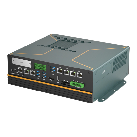
- Page 17 User’s Manual BRAV-7520 Fornt Figure 1.7 BRAV-7521 Fornt Figure 1.8...
- Page 18 User’s Manual BRAV-7520 Dimension: Unit: mm Figure 1.9 BRAV-7521 Dimension: Unit: mm Figure 1.10...
-
Page 19: Hardware Installation
User’s Manual Hardware Installation... -
Page 20: Introduction
The following sections show jumpers settings and the external connectors and pin assignments for applications. 2.2 Jumpers setting The BRAV-7520/BRAV-7521 Box Computer has a number of jumpers that allows you to configure your system to suit your application. The table below shows the function of each of the board’s Jumpers: Jumpers... -
Page 21: Atx- At/Atx Power On Mode Selection
Figure 2. 2 The BRAV-7520/BRAV-7521 provides a AT/ATX jumper, which users can set Power-on mode by it. When you set pins 2 and 3 on, it means power on by AC Power; When you set pins 1 and 2 on, it means power on by Power button. - Page 22 User’s Manual 6*USB3.1 Type A 、2*USB2.0 TypeA 2*DP, 1*VGA 3*LAN: RJ45 4*COM: DB9 1*Audio、1*Mic 3.5mm phone jake 16-bit DIO: 2*10 Pin phoenix 1*Remote SW: 1*2 Pin phoenix 1*I-port: Optional 16-bit GPIO, USB2.0 or Mini PCIe and M.2 I/O ports(such as serial ports) ...
-
Page 23: Ethernet Connector
4*2.5”SATA3 tray 2.3.1 Ethernet Connector The BRAV-7520/BRAV-7521 is equipped with 2*Intel I210AT chips and 1*Intel I219LM for 10/100/1000Mbps Ethernet controllers. The product provides 3*RJ45, with LED indicators on the front side to show its Active/Link status (Green LED) and Speed status (yellow LED). -
Page 24: Usb Connector
The USB device allows data exchange between your computer and a wide range of simultaneously accessible external Plug and Play peripherals. The BRAV-7520/BRAV-7521 provides 6*USB3.1 gen2, 2*USB2.0. The USB interface can be disabled in the system BIOS setup. Table 2.2 for USB 3.1 pin assignments. -
Page 25: Vga
VGA_z_B GND_RGB MONHSYNC VGA_5V MONVSYNC VGA_SCL 2.3.4 DP The BRAV-7520/BRAV-7521 provides 2 high-resolution DP ports, it supports the most resolution up to 4096*2160@60Hz. Table 2.5 for DP pin assignments. Figure 2. 9 Table 2.5: DP Pin Assignments Signal Signal Signal... -
Page 26: Dio Connector
User’s Manual DATA1_N CTRL DATA2_P 2.3.5 DIO Connector The BRAV-7520/BRAV-7521 provides 16-bit Iso. DIO by a 2*10pin phoenix connector, 8-bit Iso. DI(High:5-24V,Low:0-1.5V) and 8-bit Iso. DO(200mA). Table 2.6 for Pin assignments. Figure 2. 7 Table 2.6: 16-bit DIO Pin Assignments... -
Page 27: Dc Power
Figure 2. 9 Table 2.8: COM3/COM4 Serial Ports Pin Assignments Signal Signal COM_DCD COM_SIN3 COM_SOUT COM_DTR COM_DSR COM_RTS COM_CTS COM_RI 2.3.7 DC Power The BRAV-7520/BRAV-7521 provides a DC 12V power supply by 1*5pin phoenix connectors. Table 2.9 for pin assignments. -
Page 28: Serial Ata
Signal Signal 12V+ 12V+ EATH_GND 2.3.8 Serial ATA The BRAV-7520 provides 2*SATA3.0, BRAV-7521 provides 4*SATA3.0, data transfer rate up to 6Gb/s. Table 2.10 for pin assignments. Figure 2. 11 Table 2.10: Serial ATA pin assignments Signal Signal 2.3.9 Serial ATA Power Figure 2. -
Page 29: Remote Sw
PWR_BTN 2.3.11 Mini-PCIe Connector The BRAV-7520/BRAV-7521 provides a Mini PCIe. Mini PCIe interface with PCIe and USB signal, Install Mini PCI Express cards such as network cards or other cards that comply to the Mini PCI Express specifications into the Mini PCI Express slot. Table 2.13 for pin assignments. -
Page 30: Connector
+V1.5 +V3.3_MINICARD2 2.3.12 M.2 connector BRAV-7520/BRAV-7521 provides 3*M.2, 1*M.2 2280 M-Key with PCIeX4 signal, support NVMe storage; 1*H-M.2 B-Key 3052 with SIM slot and PCIeX1+USB signal, support 5G wifi; 1*H-M.2 E-Key 2230 with PCIeX1+USB signal. Table 2.14 for M.2 2280 M-Key pin assignments. Table 2.15 for M.2... - Page 31 User’s Manual Figure 2. 18 Table 2.14: M.2 2280 M-Key (NGFF)pin assignments Signal Signal +V3.3_M2 +V3.3_M2 PCIE_M2_RX24- PCIE_M2_RX24+ +V3.3_M2 PCIE_M2_TX24- +V3.3_M2 PCIE_M2_TX24+ +V3.3_M2 +V3.3_M2 PCIE_M2_RX23- +V3.3_M2 PCIE_M2_RX23+ PCIE_M2_TX23- PCIE_M2_TX23+ PCIE_M2_RX22- PCIE_M2_RX22+ PCIE_M2_TX22-...
- Page 32 User’s Manual PCIE_M2_TX22+ SSD_SATA_DEVSLP PCIE_M2_RX21- PCIE_M2_RX21+ PCIE_M2_TX21- PCIE_M2_TX21+ PLTRST_M2_N CLK_REQ6# PCIe_M2_CLK6- PCH_WAKE_N PCIe_M2_CLK6+ SUSCLK_R M.2_SSD_DET +V3.3_M2 +V3.3_M2 +V3.3_M2 Table 2.15: M.2 B-Key 3052 (NGFF1)pin assignments Signal Signal +V3_M2 +V3_M2 +V3_M2 USB_P9 WIFI_DISABLE USB_N9 +V3_M2...
- Page 33 User’s Manual SIM2_RESET SIM2_CLK SIM2_DATA SIM2_PWR SSD_SATA5_DEVSLP PCIE_RX18- PCIE_RX18+ PCIE_TX18- PLTRST_M2_N PCIE_TX18+ CLK_REQ15# CLK_PCIe_N15 PCH_WAKE_N CLK_PCIe_P15 SIM_DET +3VS SUSCLK M.2_SSD_PEDET +V3_M2 +V3_M2 +V3_M2 Table 2.16: M.2 E-Key 2230 (NGFF2)pin assignments Signal Signal +V3.3M2SB USB_P5 +V3.3M2SB USB_N5 M.2_BT_PCMCLK...
- Page 34 User’s Manual CNV_WR_D1_DN M.2_BT_PCMFRM_CRF_RST_N CNV_WR_D1_DP M.2_BT_PCMIN M.2_BT_PCMOUT_CLKREQ CNV_WR_D0_DN CNV_WR_D0_DP UART_BT_WAKE_N CNV_WR_CLK_DN M.2_CNV_BRI_DT_BT_UART0_RX M.2_CNV_RGI_DT_BT_UART0_TX CNV_WR_CLK_DP M.2_CNV_RGI_RSP_BT_UART0_CTS PCIE_X4_TX12+ M.2_CNV_BRI_DT_BT_UART0_RTS PCIE_X4_TX12- M.2_WLAN_CL_RST_N M.2_WLAN_CL_DATA PCIE_X4_RX12+ M.2_WLAN_CL_CLK PCIE_X4_RX12- DISC_WLAN_WWAN_COEX3 DISC_WLAN_WWAN_COEX2 CLK_PCIe_P14 DISC_WLAN_WWAN_COEX1 CLK_PCIe_N14 SUSCLK PLTRST_M2_N CLK_REQ14# PCH_WAKE_N CNV_WT_D1_DN CNV_WT_D1_DP PULSAR_38P4M_REFCLK CNV_WT_D0_DN GPPC_B10_CLKREQ5_WIGIG_R_N CNV_WT_D0_DP +V3.3M2SB CNV_WT_CLK_DN +V3.3M2SB CNV_WT_CLK_DP +V3.3M2SB...
-
Page 35: Pcie X4 (Brav-7521)
Figure 2. 20 2.3.15 PCIe X4 (BRAV-7520) BRAV-7520 provides 1*PCIeX4 expansion slot by ECX-255 for connecting PCIeX4 extension devices, such as motion control card, data acquisition card, etc. The maximum support is 1*75W AI acceleration card, the length of the extension card is not more than 300mm. -
Page 36: Pciex16 (Brav-7520)
Figure 2. 16 2.3.17 LED The BRAV-7520/BRAV-7521 panel has one power indicator, one hard disk indicator, three network connection status indicators, and three CPU operating temperature indicators. When the CPU operating temperature ≤85℃, the green light; When the CPU temperature is between 86℃ and 95℃, the yellow light is on, and when the CPU operating temperature is ≥96℃, the red light is on. -
Page 37: Installation
Step 2: Install a 2.5-inch hard disk into the hard disk bracket; Step 3: Put the hard drive tray back into the hard drive case; 2.4.2 HDD/SSD Installation (BRAV-7520) Step 1: unscrew the 2 screws on the HDD/SSD bracket of the rear panel. - Page 38 User’s Manual...
-
Page 39: Installing M.2
User’s Manual 2.4.3 Installing M.2 Installation steps of M.2 Module BRAV-7520 are consistent with BRAV-7521. BRAV-7521 is taken as an example below. Step 1: Unscrew the 9 screws on the side plate and remove the cover plate Step 2: Insert the corresponding M.2 module into the corresponding slot and fix it by locking the screw. -
Page 40: Installing Mini Pcie
User’s Manual 2.4.4 Installing Mini PCIe Installation steps of Mini PCIe Module BRAV-7520 are consistent with BRAV-7521. BRAV-7521 is taken as an example below. Step 1: The step here is the same as above chapter “2.4.3 Installing M.2 Module”, For details, please refer... -
Page 41: Installing Expansion Functional Module
User’s Manual 2.4.5 Installing Expansion Functional Module Installation steps of expansion functional Module BRAV-7520 are consistent with BRAV-7521. BRAV- 7521 is taken as an example below. Step 1: The step here is the same as above chapter “2.4.3 Installing M.2 Module”, For details, please refer to the above chapter “2.4.3 Installing M.2 Module”... - Page 42 User’s Manual If two GPU graphics cards need to be assembled, the following steps shall be taken to install the video card mounting bracket: (1) Assemble the GPU fixing frame and GPU adjusting frame and fix them with 8 screws (2) Fix the fixing frame on the structure with 2 screws, and the position of the GPU fixing frame can be adjusted according to the need.
- Page 43 User’s Manual...
-
Page 44: Bios Setup
User’s Manual BIOS Setup... -
Page 45: Bios Description
User’s Manual 3.1 BIOS Description BIOS is the communication bridge between hardware and software. How to correctly set the BIOS parameters is crucial for the system to work stably and whether the system works at its best. This chapter describes how to change the system settings through the BIOS settings. Note: For the purpose of better product maintenance, the manufacture reserves the right to change the BIOS items presented in this manual. -
Page 46: Bios Parameter Settings
User’s Manual 3.2 BIOS parameter settings When you start the Setup Utility, the main menu appears. The main menu of the Setup Utility displays a list of the options that are available. A highlight indicates which option is currently selected. Use the cursor arrow keys to move the highlight to other options. -
Page 47: Bios Navigation Keys
User’s Manual 3.2.1 BIOS Navigation Keys Enter the SETUP settings interface, The BIOS navigation keys are listed below: Table 3.1: The BIOS navigation keys FUNCTION Exit the current menu ↑↓→← Scrolls through the items on a menu Change Opt. Enter Select General Help Previous Values... - Page 48 User’s Manual BIOS Information This item shows the information of the BIOS vendor, version, build date and time etc. Board Information This item shows the basic information of the motherboard, including the Board ID and BIOS Version of the motherboard. Processor Information This item shows the basic information about the currently used processor, including name, type, speed, ID, core, Microcode version, etc.
-
Page 49: Advanced Menu
User’s Manual Total Memory This item shows the total memory size of the current motherboard. Memory Frequency This item shows the current memory operating frequency PCH Information This item shows the basic information about PCH, including name, model, type, etc. ME FW Version This item shows the version number of the ME firmware ME firmware SKU... - Page 50 User’s Manual CPU Configuration The configuration of the central processor, enter this sub-menu, there will be detailed details of the CPU, as well as various settings of the CPU. Power & Performance Configuration This item contains the Power & Performance configuration, enter this sub-menu, there will be detailed details of the Power &...
- Page 51 User’s Manual Hardware Monitor Hardware monitoring, enter this sub-menu, there will be CPU temperature, fan speed, status display of each common working voltage, as well as parameter settings of intelligent fan control. SIO Configuration Super IO configuration, enter this sub-menu, there will be the port configuration of the serial/parallel port which are included in IO.
-
Page 52: Chipset Menu
User’s Manual CSM (Compatibility Support Module) configuration, enter this sub-menu, there will be various settings to support UEFI startup and non-UEFI startup. If you need to start the traditional MBR device, you need to enable CSM. Turning off the CSM turns it into a pure UEFI boot. USB Configuration USB configuration, enter this sub-menu, there will be USB-related detailed settings. -
Page 53: Security Menu
User’s Manual card. PCH-IO Configuration (South Bridge Configuration) SATA And RST Configuration SATA hard disk and fast storage configuration, enter this sub-menu, there will be related settings of the hard disk. HD Audio Configuration High-fidelity audio, which controls the switch settings of the motherboard's sound card. 3.2.5 Security menu Administrator Password This item sets the information of the administrator password. -
Page 54: Boot Menu
User’s Manual 3.2.6 Boot menu Setup Prompt Timeout Setup prompts for waiting time. This option is to set the time to wait for the Del key to enter the BIOS setup after booting. Bootup NumLock State... -
Page 55: Save & Exit Menu
User’s Manual Set the state of the small numeric keypad at startup. Quiet Boot Switch full screen logo control Set Boot Priority Start device priority settings. If the user wants to install the operating system, please set "Boot Option #1" as your CD-ROM device or your U disk device (make sure that your CD-ROM drive has an operating system or your U disk has a PE system). -
Page 56: Updating The Bios
User’s Manual Save Changes; This item enables you to save the changes that you have made. Discard Changes; This item enables you to discard the changes that you have made. Restore Defaults; This item enables you to restore the system defaults. Save as User Defaults;... -
Page 57: Driver Installation
User’s Manual Driver Installation... -
Page 58: Follow The Sequence Below To Install The Drivers
User’s Manual The BRAV-7520/BRAV-7521 comes with a CD-ROM that contains all drivers and utilities that meet your needs. 4.1 Follow the sequence below to install the drivers: Figure 5. 1 Step 1 – Install Graphic Driver Step 2 – Install Audio Driver Step 3 –... -
Page 59: Utility Software Reference
User’s Manual 3. The system will help you install the driver automatically Step 5 –Install ME Driver 1. Double click on the ME folder and double click on the Setup.exe 2. Follow the instructions that the window shows 3. The system will help you install the driver automatically 4.4 Utility Software Reference All the utility software available from this page is Windows compliant. - Page 60 User’s Manual SYSTEM RESOURCE...
- Page 61 User’s Manual 5.1 WDT and GPIO /* ====================================================================== * void jhctech_init(); * function description: library initializated, This function must be called before calling other functions * parameter description: * creation date: 5*======================================================================*/ /* ====================================================================== * void jhctech_init(); * function description: library release, Pair with jhctech_init, release the library's occupied resources when not needed * parameter description:...
- Page 62 User’s Manual Parameter: port represents the number of the GPIO, 1 or 2 Mode 8 bit of a bit, each bit controls the input and output mode of a GPIO pin, Bit =1, the corresponding pin is used as the input port. Bit =0, the corresponding pin is used as an output port.
- Page 63 User’s Manual /*========================================================================== * int sio_gpio_input(WORD port); * function description:read the motherboard GPIO input level * parameter description: Return value:return a byte (8 bit), each bit of the 8-bit corresponding to the level state of a GPIO Return value Bit7 Bit6 Bit5 Bit4...
Need help?
Do you have a question about the BRAV-7520 and is the answer not in the manual?
Questions and answers