Table of Contents
Advertisement
Quick Links
Advertisement
Table of Contents

Related Manuals for JHCTech CNTI-R351


Summary of Contents for JHCTech CNTI-R351
- Page 1 User’s Manual CNTI-R351 User’s Manual Ver A0.1 Date: 28, Aug., 2023...
- Page 2 User’s Manual Version Note Ver. Note Date A0.1 first publish 2023.08.28...
- Page 3 Rockchip is a trademark of Rockchips Electronics CO., Ltd. RTL is a trademark of Realtek Semi-Conductor Co., Ltd. All other product names or trademarks are properties of their respective owners. For more information on this and other JHC products, please visit our websites at: http://www.jhctech.com.cn...
- Page 4 User’s Manual Product Warranty (2 years) JHC warrants to you, the original purchaser, that each of its products will be free from defects in materials and workmanship for two years from the date of purchase. This warranty does not apply to any products which have been repaired or altered by persons other than repair personnel authorized by JHC, or which have been subject to misuse, abuse, accident or improper installation.
- Page 5 Technical Support and Assistance Step 1. Visit the JHC web site at www.jhctech.com.cn where you can find the latest information about the product. Step 2. Contact your distributor, sales representative, or JHC’s customer service center for technical support if you need additional assistance.
-
Page 6: Table Of Contents
User’s Manual CONTENTS General Information ......................1 1.1 Introduction ............................ 2 1.2 Features............................2 1.3 Specifications ..........................2 1.3.1 General ..........................2 1.3.2 Display ..........................3 1.3.3 Ethernet ..........................3 1.3.4 Audio ..........................3 1.3.5 Power ..........................3 1.4 Environmental Specifications ....................... 3 1.5 Order Information ......................... -
Page 7: General Information
User’s Manual General Information... -
Page 8: Introduction
User’s Manual 1.1 Introduction CNTI-R351 is a domestic fan-less box computer of JHC, using SGCC box structure design, powered by Rockchip RK3588 processor, onboard RAM, 4/8/16GB LPDDR4. CNTI-R351 product provides 1*HDMI display port, 4*Gigabit network ports, 2*USB3.0, 2*USB2.0, 2* COM, 1*8bit DIO, 1*Full size Mini PCIe with SIM card slot, supports 4G LTE or other IO function modules, onboard Wifi6/BT5.0 wireless functionality, 1*M.2 2242 M-key NVMe storage, onboard 64G... -
Page 9: Display
User’s Manual Serial Ports: 2*COM (1*RS485 and 1*RS232, RS232 is a 3-wire signal, placed in one DB9 interface) USB: 2*USB3.0 TYPE A, 2*USB2.0 TYPE A DIO: 8 bit DIO Expansion Interface: 1*M.2 2242 M-key, supports NVMe storage 1*Full size Mini PCIe, with SIM card slot, supports 4G LTE or other IO function modules Onboard Wifi6/BT5.0 wireless functionality Storage: Onboard 64G eMMC, 1*M.2 2242 M-key, supporting PCIe 3.0 X2 NVMe storage... -
Page 10: Order Information
AC/DC adapter, DC12V/5A 60W 1.6 Structural Specification CNTI-R351 domestic fanless box computer is assembled by the motherboard EOM-R610 and IO subcard PIB-281, installed in the universal aluminum rectangular profile housing. Warning: Be sure to turn off the power and unplug before installation, no live operation! -
Page 11: Hardware Installation
User’s Manual Hardware Installation... -
Page 12: Introduction
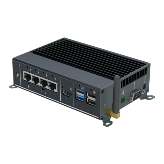
User’s Manual 2.1 Introduction The following sections describe the external and internal connectors of the product and the corresponding pin assignments. 2.2 I/O Ports CNTI-R351 Front Panel Figure 2.1 Front panel contains I/O interfaces: ⚫ Power button ⚫ 4*LAN ⚫ 2*USB3.0 Type A, 2*USB2.0 Type A ⚫... -
Page 13: Dc In
⚫ 2*COM ⚫ Remote SW ⚫ Audio out 2.2.1 DC IN The CNTI-R351 provides DC 9 to 36V power input through a 2*2pin 3.5mm pitch terminal. Table 2.1 describes the detailed pin assignment. Table 2.1: DC IN interface pin assignments Signal Signal 2.2.2 LAN... -
Page 14: Hdmi
TX+(10/100), LAN_DA+(GHz) LAN_DC-(GHz) TX-(10/100), LAN_DA-(GHz) RX-(10/100), LAN_DB-(GHz) RX+(10/100), LAN_DB+(GHz) LAN_DD+(GHz) LAN_DC+(GHz) LAN_DD-(GHz) 2.2.3 HDMI CNTI-R351 provides an HDMI display interface, and Table 2.3 provides a detailed introduction to pin allocation. 2.3: HDMI Table Pin Assignments Signal Signal Signal TX2+ HDMI_SCL... -
Page 15: Com
Table 2.5: USB2.0 TypeA Pin Assignments Signal Signal 2.2.5 COM The CNTI-R351 side panel provides one RS232 serial port and one RS485 serial port through a DB9 single-row thin-layer connector. Detailed pin assignment is described in the following table. Table 2.6:COM Pin Assignments... -
Page 16: Dio
CNTI-R351 provides one 8bit DIO through one DB9 connector, and Table 2.7 provides a detailed introduction to pin allocation. Table 2.7:DIO Pin Assignments Signal 2.2.7 CAN The CNTI-R351 side panel provides two CANs through one DB9 single row thin layer connector. The following table provides a detailed introduction to pin allocation. -
Page 17: Installation
User’s Manual Table 2.8:CAN Pin Assignments Signal CAN1H CAN1L CAN1_GND CAN2H CAN2L CAN2_GND 2.3 Installation 2.3.1 Mini PCIe/M.2 2242 M-key module installation Step 1: Unscrew the six screws on the right panel and remove the right panel; Step 2: Unscrew the 8 screws on the left panel and remove the left panel;... - Page 18 User’s Manual Step 3: Take off the bottom cover; Step 4: Hold the Mini PCIe/M.2 2242 M-key module so that its notch is aligned with the Mini PCIe/M.2 2242 M-key slot on the board, insert it into the socket at a 30 degree angle, and tighten 1 screw to secure the installed module;...
- Page 19 User’s Manual Step 5: Follow the disassembly steps and use the reverse steps to complete the product installation.
Need help?
Do you have a question about the CNTI-R351 and is the answer not in the manual?
Questions and answers