Table of Contents
Advertisement
Quick Links
Advertisement
Table of Contents

Related Manuals for JHCTech BRAV-7123


Summary of Contents for JHCTech BRAV-7123
- Page 1 用户手册 BRAV-7123 User’s Manual Ver.A0.1 Date:2025-2-7...
- Page 2 Microsoft Windows and MS-DOS are registered trademarks of Microsoft Corp. RTL is a trademark of Realtek Semi-Conductor Co., Ltd. All other product names or trademarks are properties of their respective owners. For more information on this and other JHC products, please visit our websites at: http://www.jhctech.com.cn...
-
Page 3: Product Warranty (2 Years)
User’s Manual Product Warranty (2 years) JHC warrants to you, the original purchaser, that each of its products will be free from defects in materials and workmanship for two years from the date of purchase. This warranty does not apply to any products which have been repaired or altered by persons other than repair personnel authorized by JHC, or which have been subject to misuse, abuse, accident or improper installation. -
Page 4: Declaration Of Conformity
Technical Support and Assistance Step 1. Visit the JHC web site at www.jhctech.com.cn where you can find the latest information about the product. Step 2. Contact your distributor, sales representative, or JHC’s customer service center for technical support if you need additional assistance. -
Page 5: Table Of Contents
User’s Manual CONTENTS General Information ..........................1 1.1 Introduction ............................2 1.2 Features ..............................2 1.3 Specifications ............................2 1.3.1 General ..................................2 1.3.2 Graphics ..................................3 1.3.3 Ethernet ..................................3 1.3.4 Audio ..................................... 3 1.3.5 Power Consumption ..............................4 1.4 Environmental requirement ........................4 1.5 Ordering Information ........................... - Page 6 User’s Manual 2.2.8 M.2 B-Key 3042/3052 (4G/5G) ........................... 12 2.2.10 M.2 M-Key 2280 (NVME) ............................13 2.3 Installation ............................15 2.3.1 M.2 2230 E-key module Install ............................15 2.3.2 M.2 2280 M-Key module Install ..........................15 2.3.3 M.2 3052 B-Key module Install ........................... 16...
-
Page 7: General Information
User’s Manual General Information... -
Page 8: Introduction
User’s Manual 1.1 Introduction BRAV-7123 is a product of NVIDIA Jetson Orin platform for MEC edge computing with high performance and high power. It is equipped with NVIDIA Jetson NX Orin 8/16GB module, 8/12 core ARM CPU and high-performance GPU, and the highest AI performance can reach 70~157TOPS. -
Page 9: Graphics
User’s Manual GPU: 1024*Cores NVIDIA Ampere Architecture GPU 765MHz, with 32*Tensor Cores(S001); 1024*Cores NVIDIA Ampere Architecture GPU 918MHz, with 32*Tensor Cores(S002) DL Accelerator & VS Accelerator: 1*NVDLA v2(S001)/2*NVDLA v2(S002), PVA v2.0 Memory: Onboard 8GB(S001)/16GB(S002) 128-bit LPDDR5, the maximum bandwidth up to 102.4GB/s USB: 6*USB3.0(Type A),2*USB2.0(Type A) Serial... -
Page 10: Power Consumption
With SSD: 50g peak acceleration (continue 11ms) ; with HDD: 20g peak acceleration (continue 11ms) EMC: CE, FCC Class A 1.5 Ordering Information Model No. Module Introduction BRAV-7123-S001 Jetson Orin NX 8GB 1*HDMI,2*GBE RJ45,6*USB3.0,2*USB2.0,2*RS485,2*Iso. CAN FD, 2*Speaker,1*Mic,1*M.2 B-Key w/SIM,1*M.2 E-key,DC-IN 9~36V, BRAV-7123-S002 Jetson Orin NX16GB PA-120DC12 AC/DC power adapter,DC19V/5A,60W... -
Page 11: I/O Interface
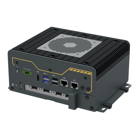
User’s Manual 1.6 I/O Interface BRAV-7123 front view: Figure 1. 1 I/O interface included on the front panel: DC IN 9-36V 1*HDMI 2*Gig-LAN 6*USB3.0 2*USB 2.0 2*ANT 1*Power button... - Page 12 User’s Manual BRAV-7123 rear view: Figure 1. 2 I/O interface included on the rear panel: 1*MIC 2*Speaker 2*RS485 2*CAN 4*ANT 1*SIM...
-
Page 13: Dimension
User’s Manual 1.7 Dimension BRAV-7123 Dimension(Unit:mm) Figure 1.4 Figure 1.5 Figure 1.6... -
Page 14: Hardware Installation
User’s Manual Hardware Installation... -
Page 15: Introduction
User’s Manual 2.1 Introduction The following chapters will state the panel DIP switch settings and external connectors and pin assignments of the product. 2.2 I/O Introduction and Pin Assignments 2.2.1 DC-IN DECA 3Pin terminal 3.81mm Pitch Figure 2.1 DC-IN Table 2.1: DC-IN Port Pin Assignment Signal Signal 9~36V... -
Page 16: Hdmi 2.0
User’s Manual 2.2.3 HDMI 2.0 PIB-319 provides a vertical HDMI display interface with a detailed pin assignment described below. Figure 2.3 HDMI interface Table 2.3: HDMI Port Pin Assignments Signal Signal Signal DATA2_P DATA0_N DATA2_N CLK_P DATA1_P CLK_N DETECT DATA1_N DATA0_P 2.2.4 2*LAN(LAN1/LAN2)... -
Page 17: Usb3.0
User’s Manual 2.2.5 6*USB3.0 PIB-319 provides one PCIeX4 to USB3.0 * 4 Type-A port, four USB3.0 interfaces, and two USB3.0 Type A interfaces through USB 3.0 double-layer connector. The following table assigns the pins. Figure 2.5 USB3.0 Table 2.5 : USB3.0 type A Port Pin Assignments Signal Signal VBUS... -
Page 18: B-Key 3042/3052 (4G/5G)
User’s Manual Figure 2.7 2*5 Phoenix terminal Table 2.7: COM1/2、CAN1/2 Port Pin Assignments Signal Signal CANL2 DATA_A2 CANH2 DATA_B2- CANL1 DATA_A1 CANH1 DATA_B1 2.2.8 M.2 B-Key 3042/3052 (4G/5G) Band PCIe x 2 + USB2.0, connected to SIM Slot, support 4G or 5G Figure 2.8 M.2 B-Key slot Table 2.8 : M.2 B-Key 3042/3052 Port Pin Assignments Signal... -
Page 19: M-Key 2280 (Nvme)
User’s Manual SIM2_PWR SSD_SATA5_DEVSLP PCIE_RX18- PCIE_RX18+ PCIE_TX18- PCIE_TX18+ PLTRST_M2_N CLK_REQ15# CLK_PCIe_N15 PCH_WAKE_N CLK_PCIe_P15 SIM_DET +3VS SUSCLK M.2_SSD_PEDET +V3_M2 +V3_M2 +V3_M2 2.2.10 M.2 M-Key 2280 (NVME) Signal band PCIe x1 to realize NVME Storage storage expansion Figure 2.9 M.2 M-Key slot Table 2.9: M.2 M-Key Port Pin Assignments Signal Signal... - Page 20 User’s Manual USB_D+ USB_D- +V3.3_M2 +V3.3_M2 +V3.3_M2...
-
Page 21: Installation
User’s Manual 2.3 Installation This section describes how to install the M. 2230 E-key module, M. 2280 M-key module and M. 2 3052 B-key module. 2.3.1 M.2 2230 E-key module Install Step 1: Disassemble and disassemble the machine. Step 2: align the slot of the M.2 module at the slot on the motherboard (below Figure red box), and insert it at a 30 degree Angle with the slot. -
Page 22: 3052 B-Key Module Install
User’s Manual Figure 2.11 Step 3: Attach the M.2 module to the bracket with a screw. Step 4: Complete the installation of the product according to the reverse disassembly step. 2.3.3 M.2 3052 B-Key module Install Step 1: Disassemble and disassemble the machine. Step 2: align the slot of M.2 module at the slot on the motherboard (red box below) and insert it at a 30 degree Angle with the slot. - Page 23 User’s Manual Figure 2.12 Step 3: Attach the M.2 module to the bracket with a screw. Step 4: Complete the installation of the product according to the reverse disassembly step.
Need help?
Do you have a question about the BRAV-7123 and is the answer not in the manual?
Questions and answers