Advertisement
Quick Links
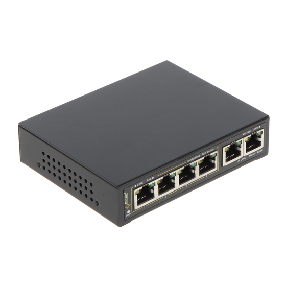
Switch 6 ports
4 PoE ports 10/100/100Mb/s (data and power supply)
2 ports 10/100/1000Mb/s (UP LINK)
30W for each PoE port, supports devices complaint
with the IEEE802.3af/at standard
Supports auto-learning and auto-aging of MAC
addresses (1K size)
LED indication
1. Technical description
1.1. General description.
The SG64-C is a complete kit to build the CCTV system based on IP cameras. The switch and power supply unit are
housed in a metal enclosure.
Automatic detection of any devices powered in the PoE standard is enabled at the 1 – 8 ports of the switch. The
UP LINK ports is used for connection of another network device via RJ45 connector. The LEDs at the front panel indicate the
operation status (description in the table below).
The PoE technology ensures a network connection and reduces installation costs by eliminating the need to supply a
separate power cable for each device. This method allows supplying other network devices, such as IP phone, wireless access
point or router.
SG64-C
v1.0
SG64-C 6-ports switch for 4 IP cameras
in the enclosure
Edition: 1 from 04.01.2018
Supercedes the edition: ---------
Features
:
Metal enclosure – color white RAL 9003
warranty – 2 year from the production date
Example of use.
1
PL
EN**
Advertisement

Subscribe to Our Youtube Channel
Related Manuals for Pulsar SG64-C


Summary of Contents for Pulsar SG64-C
- Page 1 1. Technical description 1.1. General description. The SG64-C is a complete kit to build the CCTV system based on IP cameras. The switch and power supply unit are housed in a metal enclosure. Automatic detection of any devices powered in the PoE standard is enabled at the 1 – 8 ports of the switch. The UP LINK ports is used for connection of another network device via RJ45 connector.
- Page 2 1.2 Block diagram. Fig. 1. Block diagram. 1.3 Description of components and connectors. Table 1. (See Fig. 2) Component No. Description (Fig. 2) Switch Switch mode buffer power supply unit (PS-604812), 48VDC/1,2A/60W Potentiometer adjusting the output voltage of the power supply (48÷53V) LED light –...
- Page 3 Table 2. ( See Fig . 3) Component No Description (Fig. 3) 2 x UP LINK port 4 x PoE ports (1÷4) 48VDC power supply socket Fig. 3. The view of the switch. 1.4 Technical parameters (tab.3) Table 3. 6 ports 10/100/1000Mb/s (4 x PoE + 2 x UP LINK) Ports with connection speed auto-negotiation and MDI/MDIX Auto Cross) IEEE 802.3af/at (1÷4 ports), 48V DC / 30W at each port *...
- Page 4 2. Installation 2.1. Requirements 1. The device should be mounted by a qualified installer, holding relevant permits and licenses (applicable and required for a given country) for 230V/AC and low-voltage installations. 2. The device shall be mounted in confined spaces, according to the environment class II, with normal air humidity (RH=90% max.
- Page 5 3. Operation indication. Table 4. Operation indication OPTICAL INDICATION OF THE SWITCH's POWER SUPPLY GREEN LED LIGHT (Power) OFF – no power supply of the switch Indication of the switch's ON – power supply on, normal operation power supply OPTICAL INDICATION AT THE PoE PORTS (1÷4) GREEN LED LIGHT (PoE) OFF- no power supply at the RJ45 port (the device is not connected or not compliant Indication of the PoE power...
-
Page 6: Weee Label
Waste electrical and electronic equipment must not be disposed of with normal household waste. According to the European Union WEEE Directive, waste electrical and electronic equipment should be disposed of separately from normal household waste Pulsar Siedlec 150, 32-744 Łapczyca, Poland Tel. (+48) 14-610-19-40, Fax. (+48) 14-610-19-50 e-mail: biuro@pulsar.pl, sales@pulsar.pl http:// www.pulsar.pl, www.zasilacze.pl...
Need help?
Do you have a question about the SG64-C and is the answer not in the manual?
Questions and answers