Table of Contents
Advertisement
Advertisement
Table of Contents

Related Manuals for IBM 9306


Summary of Contents for IBM 9306
- Page 1 Hardware Maintenance Manual IBM PC Server/Enterprise Racks Types 9306, 9308...
- Page 3 Hardware Maintenance Manual IBM PC Server/Enterprise Racks Types 9306, 9308...
- Page 4 This publication was developed for products and services offered in the United States of America. IBM may not offer the products, services, or features discussed in this document in other countries, and the information is subject to change without notice.
-
Page 5: Table Of Contents
Parts Listing (Type 9306 Model 200) ....32 Type 9306 Model 900/910 ..... 34 Features . - Page 6 Installing a monitor shelf ..... 120 IBM NetBAY Console Switch ....121 Features .
- Page 7 NetBAY Power Distribution Units ....130 NetBAY rack Power Distribution Unit introduction ... . 130 Tool requirements .
- Page 8 Grounding requirements ....231 Problem determination tips ....231 Hardware Maintenance Manual: IBM PC Server/Enterprise Racks Types 9306, 9308...
-
Page 9: About This Manual
About this manual This manual contains diagnostic information, a Symptom-to-FRU index, service information, error codes, error messages, and configuration information. Important: This manual is intended for trained servicers who are familiar with IBM PC Server products. Important safety information Be sure to read all caution and danger statements in this book before performing any of the instructions. - Page 10 Hardware Maintenance Manual: IBM PC Server/Enterprise Racks Types 9306, 9308...
-
Page 11: General Checkout
General Checkout Use the following procedure for diagnosing keyboard, mouse, and video problems for the IBM PC Server Rack Enclosure and the IBM Rack enclosures (Type 9306 and Type 9308). For power problems, see “Power checkout” on page 2. Attention:... -
Page 12: Power Checkout
Server selector keypad e. Server selector unit Power checkout Use the following procedure for diagnosing power problems for the IBM PC Server Rack Enclosure and IBM Rack enclosure (Type 9306). Attention: v For Models 4QS, 4QX, 9QS, 9QX, 9TS, 9TX only: Ensure that the voltage selector switch on each server installed in the server rack is set to 230 V ac. -
Page 13: Powering Off The Rack
2. Power-off the server selector unit. 3. If a UPS system is installed in the rack, power-off the UPS system. 4. Disconnect power from the IBM PC Server Rack. v If the rack is plugged into a wall-mounted power supply, disconnect the power cord plug from the wall socket. - Page 14 Hardware Maintenance Manual: IBM PC Server/Enterprise Racks Types 9306, 9308...
-
Page 15: Type 9306 Model 250/420/421
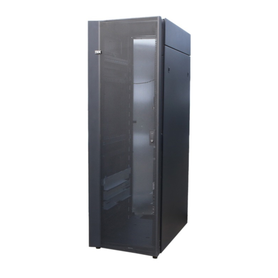
Type 9306 Model 250/420/421 Features The IBM NetBAY 42, Type 9306, Model 420 with side panels, Model 421 without side panels and the IBM NetBAY 25, Type 9306, Model 250. NetBAY 42 and NetBAY 25 Cabinets ® ® This documentation contains general installation instructions for the IBM NetBAY25 and NetBAY42 Rack cabinets, and many of the common optional devices that you can install in a rack cabinet. -
Page 16: Installing A Rack Cabinet
You can install the new side or filler panel FRUs on either type of rack cabinet. 1. One U is equal to 4.45 cm (1.75 in.) Hardware Maintenance Manual: IBM PC Server/Enterprise Racks Types 9306, 9308... - Page 17 This process ensures that the end product remains safe for the operator and service personnel under normal and forseeable misuse conditions. Figure 2. NetBAY25 Rack cabinet Type 9306 Model 250/420/421...
- Page 18 Figure 3. Primary NetBAY42 Rack cabinet with side panels Hardware Maintenance Manual: IBM PC Server/Enterprise Racks Types 9306, 9308...
- Page 19 Figure 4. Expansion NetBAY42 Rack cabinet without side panels Type 9306 Model 250/420/421...
- Page 20 2. Attach the stabilizer bracket to the front of the rack cabinet with the screws that come with the bracket. 3. If necessary, bolt the rack cabinet to the floor through the provided holes in the stabilizer bracket. Hardware Maintenance Manual: IBM PC Server/Enterprise Racks Types 9306, 9308...
- Page 21 Figure 6. Front stabilizer bracket Figure 7. Installing the NetBAY42 front stabilizer bracket 3. Attach the front stabilizer bracket to the front of the rack cabinet with the screws that come with the bracket. Type 9306 Model 250/420/421...
- Page 22 3. Repeat this procedure to remove both side panels. Reverse this procedure to install the side panels. Slide both locking bars into the locked position to secure the side panel to the rack cabinet. Hardware Maintenance Manual: IBM PC Server/Enterprise Racks Types 9306, 9308...
- Page 23 Removing and installing NetBAY42 panels The primary NetBAY42 Rack cabinet comes with side panels installed. Remove the side panels from a primary rack cabinet, or the outermost rack cabinets in a suite, before you install or remove optional devices. Type 9306 Model 250/420/421...
- Page 24 3. Repeat this procedure to remove both side panels. Reverse this procedure to install the side panels. Slide both locking bars into the locked position to secure the side panel to the rack cabinet. Hardware Maintenance Manual: IBM PC Server/Enterprise Racks Types 9306, 9308...
- Page 25 Installing rear filler panels: Use the following procedure to install the rear filler panels on the rack cabinet: 1. Align the bottom of the rear filler panel with the tab on the bottom rear of the rack cabinet. Type 9306 Model 250/420/421...
- Page 26 FRU on NetBAY25 and NetBAY42 rack cabinets. See the following illustrations of the two styles of latches. Note: Doors that come with square latches are slightly thicker and heavier than doors that come with round latches. Hardware Maintenance Manual: IBM PC Server/Enterprise Racks Types 9306, 9308...
- Page 27 1. Unlock and open the door. 2. Grasp the door firmly with both hands and lift it upward and away from the hinges; then, set the door aside. Reverse this procedure to install the door on the rack cabinet. Type 9306 Model 250/420/421...
- Page 28 Reverse this procedure to install the door on the rack cabinet. Reversing a front or rear door: Use the following procedure to reverse a front or rear door on the rack cabinet so that it opens in the opposite direction: Hardware Maintenance Manual: IBM PC Server/Enterprise Racks Types 9306, 9308...
- Page 29 3. Remove the front door latch and attach it to the other side of the rack cabinet. Note: The rear door latch is built-in to both rear filler panels, so there is nothing to move when reversing the rear door on the rack cabinet. Type 9306 Model 250/420/421...
- Page 30 4. Carefully rotate the door 180°; then, install the door on the other side of the rack cabinet. Figure 15. Rotating and installing the door Hardware Maintenance Manual: IBM PC Server/Enterprise Racks Types 9306, 9308...
- Page 31 5. Remove the IBM logo from the bottom of the door; then, snap it into place near the top of the perforated section of the door. Figure 16. Moving the IBM logo Type 9306 Model 250/420/421...
- Page 32 Use the bolts and nuts that come with the expansion rack cabinet to attach the rack cabinets to each other. 4. Install the panels that you removed in step 1 on the expansion rack cabinet. Hardware Maintenance Manual: IBM PC Server/Enterprise Racks Types 9306, 9308...
- Page 33 Always read the instructions that come with your server or optional device for detailed cable-management information. Use the following general guidelines when cabling servers or optional devices that you install in a rack cabinet: Statement 8: Type 9306 Model 250/420/421...
- Page 34 FRU on either type of rack cabinet. If you install these brackets on a rack cabinet that did not originally come with them, you cannot use a screw to secure the filler panels unless you also install the new filler panels. Hardware Maintenance Manual: IBM PC Server/Enterprise Racks Types 9306, 9308...
- Page 35 Fully populated NetBAY25 and NetBAY42 Rack cabinets have been evaluated and found to meet UL-1950, CSA-950, and IEC-950 stability test standards. Because these standards apply only to a rack cabinet in an installed location, IBM enforces additional standards to ensure stability when rolling the rack cabinet on its casters.
- Page 36 Connect all devices installed in a rack cabinet to power devices installed in the same rack cabinet. Do not plug a power cord from a device installed in one rack cabinet into a power device installed in a different rack cabinet. Hardware Maintenance Manual: IBM PC Server/Enterprise Racks Types 9306, 9308...
- Page 37 Pack the rack cabinet in the original packaging material, or equivalent. Also, lower the leveling pads to raise the casters off of the pallet and strap the rack cabinet to the pallet. Type 9306 Model 250/420/421...
-
Page 38: Part Listing (Type 9306)
25U Rear Symm Front Panel MTG. MBR (Model 250) 32P1011 42U Base Cross Box (Models 420, 421) 32P1015 25U Base Cross Box (Model 250) 32P1013 42U x 600 x 1000 Rack Framework Only (Models 420, 421) 06P6054 Hardware Maintenance Manual: IBM PC Server/Enterprise Racks Types 9306, 9308... - Page 39 Index Rack Enclosure (Type 9306) 25U x 600 x 1000 Rack Framework Only (Model 250) 32P1010 Swivel Caster (Models 250, 420, 421) 06P6055 Swivel Caster (Models 250, 420, 421) 06P6055 Cable management bracket( Model 250) 32P1784 Cable management bracket( Models 420, 421)
- Page 40 Hardware Maintenance Manual: IBM PC Server/Enterprise Racks Types 9306, 9308...
-
Page 41: Type 9306 Models 200/900/910
Type 9306 Models 200/900/910 Type 9306 Models 900/910 Features The IBM NetBAY22, Type 9306, Model 200 Rack enclosure is a 22-U (1-U = 1.75 inch) industry-standard, 19-inch rack that houses and controls multiple IBM PC Servers/IBM Servers and related equipment. -
Page 42: Parts Listing (Type 9306 Model 200)
Parts Listing (Type 9306 Model 200) Hardware Maintenance Manual: IBM PC Server/Enterprise Racks Types 9306, 9308... - Page 43 Combination Head Screw (6), 10-32 Flat Washer (6), M6X12 Button Socket Head Cap Screw (5), 12mm Open End Wrench (1), M6 Tinnerman Clip (2), M6 Threaded Hex Spacer (1), M6 Dome Nut (2), M6 Flange Nut (5), Soft Tie Wraps (10) Rack Enclosure (Type 9306 Model 200) Options Monitor Housing 76H4947...
-
Page 44: Type 9306 Model 900/910
Cable Access Cover (1), Bottom Stand Type 9306 Model 900/910 Features The IBM Server 9306-900/910 Rack enclosure is an industry-standard, 19-inch rack that houses and controls multiple IBM PC Servers/IBM Servers and related equipment. v Model 900 has optional side panels, solid front door, and perforated rear door. - Page 45 Perforated Doors (model 910) The Type 9306 Model 910 Rack comes with front and rear perforated doors that provide enhanced cooling and airflow for components you install in your rack cabinet. The 9306 Model 910 Rack also comes with side panels already installed.
- Page 46 4. Remove the screw and nut that holds the hinge bracket 1 in place; then, move the hinge bracket 2 three mounting spaces downward and reinstall it at the new center location. Hardware Maintenance Manual: IBM PC Server/Enterprise Racks Types 9306, 9308...
- Page 47 6. While supporting the new door, use three of the hinge pins that you removed from the old door to attach the new door to your rack cabinet. Store the fourth hinge pin with the old door and hinge bracket. 7. Reinstall the left side panel that you removed earlier. Type 9306 Models 200/900/910...
-
Page 48: Parts Listing (Type 9306 Model 900/910)
Parts listing (Type 9306 Model 900/910) Hardware Maintenance Manual: IBM PC Server/Enterprise Racks Types 9306, 9308... - Page 49 M6 Tinnerman Clip (2) M6 Threaded Hex Spacer (1) M6 Dome Nut (2) M6 Flange Nut (5) Soft Tie Wraps (10) Rack Enclosure (Type 9306 Model 900/910) Options Monitor Housing 76H4947 Side Panel Lock with Keys 76H4965 Side Panel Latch...
- Page 50 (4); M4 X 8 Screw (2); 14 inch Soft Tie Wrap (1); T54A power supply spacer (1) Flat Panel Adapter Display Housing – Includes: Power Supply Cover (1); Base 00N8694 Housing (1); Cable Access Cover (1); Bottom Stand Hardware Maintenance Manual: IBM PC Server/Enterprise Racks Types 9306, 9308...
-
Page 51: Type 9306 Models 4Qs, 4Qx, 9Qs, 9Qx, 9Ts, 9Tx
Type 9306 Models 4QS, 4QX, 9QS, 9QX, 9TS, 9TX Features The 9306 IBM PC Server Rack Enclosure, models 4QS, 9QS, 9TS come in three primary models. v 19-inch Quad Primary Server Rack, Model 9QS v 19-inch Tri Primary Server Rack, Model 9TS v 24-inch Quad Primary Server Rack, Model 4QS A Quad Primary Server Rack can house up to four IBM PC Servers. -
Page 52: Server Selector Unit
Cable Server selector unit The server selector unit is located in the upper rear of the rack cabinet. The server selector unit can only be accessed or removed from the rear of the IBM Rack cabinet. CAUTION: The server selector unit is heavy. You will need two people to safely remove the server selector unit. -
Page 53: Connections
Note: To remove the power distribution unit, you might need to remove the right side cabinet panel, the server installed in sliding tray 2 (in the primary IBM PC Server Rack), or sliding tray 5 (in the IBM PC Server Expansion Rack). -
Page 54: Cooling Fan
Note: When installing the fan, make sure that the green and yellow ground wire is attached to one of the top fan mounting screws and that the strain-relieving clamp is attached to another. The power cable should be secured by the Hardware Maintenance Manual: IBM PC Server/Enterprise Racks Types 9306, 9308... -
Page 55: Sliding Trays
6. Release the forward locking tab 5 . Then, while holding the sliding tray in place, use your other hand to grasp the outside sliding rail 6 and push it into the rack cabinet until it disconnects from the sliding tray. Type 9306 Models 4QS, 4QX, 9QS, 9QX, 9TS, 9TX... -
Page 56: Sliding Rails
2. Remove the sliding tray that is attached to the sliding rails that you want to remove. See “Sliding trays” on page 45. 3. Use a 3/32-inch allen wrench to remove the four screws that secure each of the sliding rails to the rack cabinet. Hardware Maintenance Manual: IBM PC Server/Enterprise Racks Types 9306, 9308... -
Page 57: Keyboard Tray
2. Disconnect the keyboard and mouse cables from the keyboard and mouse extension cables. 3. Remove the keyboard and mouse from the keyboard tray. 4. Pull the keyboard tray straight out of the rack cabinet. Type 9306 Models 4QS, 4QX, 9QS, 9QX, 9TS, 9TX... -
Page 58: Parts Listing (Type 9306 - 19-Inch) Models 9Qs, 9Ts And 9Qx, 9Tx
Parts listing (Type 9306 – 19-inch) Models 9QS, 9TS and 9QX, 9TX This parts listing is for Models 9QS, 9TS and 9QX, 9TX Hardware Maintenance Manual: IBM PC Server/Enterprise Racks Types 9306, 9308... - Page 59 Slide Rails, Dual Tray (one pair) 76H0383 19-inch Front Compartment Door (19-Inch by 26-Inch) Includes Hinge Set and Screws 76H0371 Door Hinge Set 76H0372 Door Valance (9QX, 9TX, Expansion units only) 76H0380 Mouse Table 07H0079 Type 9306 Models 4QS, 4QX, 9QS, 9QX, 9TS, 9TX...
- Page 60 Whiz-Lock Flange Nut 1/4-20 (2 each) v Keeper Nut 10-32 (2 each) v Bumpers (2 each) v Cable Ties (8 each) Server Tray Interlock Kit 07H0091 v Cam (1 each) v Spring (1 each) Hardware Maintenance Manual: IBM PC Server/Enterprise Racks Types 9306, 9308...
-
Page 61: Parts Listing (Type 9306 - 24-Inch) Models 4Qs, 4Qx
Parts listing (Type 9306 – 24-inch) Models 4QS, 4QX This parts listing is for Models 4QS and 4QX. 10 11 Type 9306 Models 4QS, 4QX, 9QS, 9QX, 9TS, 9TX... - Page 62 Monitor Power Cable (connects from monitor to Power Distribution Unit) 07H0075 Rack Keyboard Cable (connects from Keyboard Drawer to Server Selector Unit) 07H0067 Rack Mouse Cable (connects from Keyboard Drawer to Server Selector Unit) 07H0069 Hardware Maintenance Manual: IBM PC Server/Enterprise Racks Types 9306, 9308...
- Page 63 34-Inch (1 each); Spacer, Body 70-Inch (2 each); Screw 10-32 x 3/8 Button Head Socket cap; (8 each); Screw 1/4-20 x 1/2 Button Head Socket cap; (8 each); Whiz-Lock Flange Nut 1/4-20 (8 each); Screw 6-32 x 3/8 Button Head Socket Cap; (6 each) Type 9306 Models 4QS, 4QX, 9QS, 9QX, 9TS, 9TX...
- Page 64 Hardware Maintenance Manual: IBM PC Server/Enterprise Racks Types 9306, 9308...
-
Page 65: Netbay 42 Enterprise Rack (Type 9308 Models 42P, 42X, 4Sa, 4Sb, 42S, 42E)
NetBAY 42 Enterprise Rack (Type 9308 Models 42P, 42X, 4SA, 4SB, 42S, 42E) Features The IBM NetBAY 42 Enterprise Rack (Type 9308 – Models 42P, 42X, 4SA, 4SB, 42S, 42E) enclosure is an industry-standard, 19-inch rack cabinet that houses multiple IBM servers and related equipment. - Page 66 Primary Rack (Model 42P) Hardware Maintenance Manual: IBM PC Server/Enterprise Racks Types 9306, 9308...
- Page 67 Extension Rack (Model 42X) NetBAY 42 Enterprise Rack (Type 9308 Models 42P, 42X, 4SA, 4SB, 42S, 42E)
- Page 68 Primary Rack (42S) Hardware Maintenance Manual: IBM PC Server/Enterprise Racks Types 9306, 9308...
-
Page 69: Locations
Expansion Rack (42E) Locations The following sections contain information on specific equipment locations. The primary rack cabinet comes with side panels installed. Remove the side panels from a primary rack cabinet, or the outermost rack cabinets in a suite, before you install or remove optional devices. - Page 70 Removing and installing the top 6U side panels Use the following procedure to remove the top 6U side panels from the rack cabinet: Hardware Maintenance Manual: IBM PC Server/Enterprise Racks Types 9306, 9308...
-
Page 71: Doors
Figure 20. Removing the top 6U side panels from the rack cabinet 1. On the top of the rack cabinet, loosen the four screws that hold each side panel in place. 2. Tilt the side panel slightly toward you; then, remove it from the rack cabinet. 3. - Page 72 2 . Notes: 1. Reverse this procedure to reinstall front and rear doors. 2. The top hinge pin is longer than the bottom; engage it first when you reinstall doors. Hardware Maintenance Manual: IBM PC Server/Enterprise Racks Types 9306, 9308...
- Page 73 Rear door – Models 42S, 42E Use the following procedure to remove a rear door from the rack cabinet: Rear door Bottom hinge pin Figure 21. Removing a rear door from the rack cabinet 1. Unlock and open the rear door. 2.
- Page 74 Front door Hinge pin latch Hinge pin Figure 22. Removing a front door from the rack cabinet Hardware Maintenance Manual: IBM PC Server/Enterprise Racks Types 9306, 9308...
-
Page 75: Removing And Installing The Top 6U Portion Of The Rack
1. Unlock and open the front door. 2. While supporting the door, lift the bottom hinge-pin latch and move it clockwise to unlock the bottom hinge pin; then, unlock the top hinge pin. 3. Pull the door away from the rack cabinet; then, set the door aside. Reverse this procedure to install the front door on the rack cabinet. -
Page 76: Installing The Stabilizer Bracket
Expansion rack cabinets come with all the hardware required for you to attach rack cabinets together and form a suite. Use the following procedure to attach rack cabinets together in a suite: Hardware Maintenance Manual: IBM PC Server/Enterprise Racks Types 9306, 9308... - Page 77 Trim piece Threaded standoff Bolt and washer Figure 24. Attaching two adjacent rack cabinets to each other to form a suite 1. Remove both side panels (see “Removing and installing the side panels” on page 59) from the side of a primary rack cabinet that is adjacent to an expansion rack in a suite.
-
Page 78: Installing L-Channel Support Rails To Rack Mounting Brackets
From left to right, the illustration shows the front and rear flanges respectively. Front Rear Hardware Maintenance Manual: IBM PC Server/Enterprise Racks Types 9306, 9308... - Page 79 Note: Use clip nuts if your rack has circular holes. If your rack has square holes, you can use the rack-insertion tool or a flat-blade screwdriver to install cage nuts. 2. On the rail marked R, loosen the four screws 2 . 3.
- Page 80 Use safe practices when lifting. 7. Slide the expansion unit into the rack, and insert the M6 screws 1 . Do not overtighten the M6 1 screws. 8. Tighten the rear screws 2 . Hardware Maintenance Manual: IBM PC Server/Enterprise Racks Types 9306, 9308...
-
Page 81: Parts Listing (Type 9308 Model 42P, 42X)
Parts listing (Type 9308 Model 42P, 42X) Index Rack Enclosure (Type 9308 Model 42P, 42X, 4SA, 4SB, 42S, 42E) Top Cover Assembly including cover standoffs and screws (All models) 05N4896 Cabinet Frame (All models) 05N4895 Front Door w/Lock (Models 42P, 42X) 05N4897 Rear Door w/Lock (Models 42P, 42X) 05N4899... - Page 82 Screw (2); 14 inch Soft Tie Wrap (1); T54A power supply spacer (1) Flat Panel Adapter Display Housing – Includes: Power Supply Cover (1); Base Housing (1); 00N8694 Cable Access Cover (1); Bottom Stand Hardware Maintenance Manual: IBM PC Server/Enterprise Racks Types 9306, 9308...
-
Page 83: Netbay3 Enclosure
Note: Vertical measurements are given in rack units (U). One U is equal to 4.45 cm (1.75-inches). Up to three NetBAY3 enclosures can be stacked under certain IBM servers. Devices such as the IBM EXP10, an uninterruptable power supply (UPS), or various telecommunications equipment can also be installed in a NetBAY3 enclosure. Locations The following sections contain information on specific equipment locations. -
Page 84: Foot Pads
Foot pads Front cover Hardware Maintenance Manual: IBM PC Server/Enterprise Racks Types 9306, 9308... -
Page 85: Rear Panel
Rear panel Note: Make sure empty NetBAY3 enclosures (no devices installed) have the rear cover securely attached. NetBAY3 enclosure... -
Page 86: Device Side Rails
Device side rails Stacking NetBAY3 enclosures Note: Make sure NetBAY3 enclosures in a stack are securely fastened together. Hardware Maintenance Manual: IBM PC Server/Enterprise Racks Types 9306, 9308... - Page 87 Note: The maximum server weight is 77 kg (170 lb.). NetBAY3 enclosure...
-
Page 88: Parts Listing (Netbay3)
03K8799 Miscellaneous Parts Kit - Includes: 03K9056 v M6 Caged Nuts (2) v M6X16 Combination Head Screw (2) v M6X14 Flanged Hex Head Screw (2) v M5 Flange Nut (2) Hardware Maintenance Manual: IBM PC Server/Enterprise Racks Types 9306, 9308... -
Page 89: Netbay3E Enclosure
Note: Vertical measurements are given in rack units (U). One U is equal to 4.45 cm (1.75-inches). Up to three NetBAY3E enclosures can be stacked under certain IBM servers. Devices such as the IBM EXP10, an uninterruptable power supply (UPS), or various telecommunications equipment can also be installed in a NetBAY3E enclosure. Important: v The maximum server weight is 77 kg (170 lb.). -
Page 90: Front Cover
Front cover Hardware Maintenance Manual: IBM PC Server/Enterprise Racks Types 9306, 9308... -
Page 91: Rear Panel
Rear panel Note: Make sure empty NetBAY3E enclosures (no devices installed) have the rear cover securely attached. Device side rails Stacking NetBAY3E enclosures Notes: 1. Make sure NetBAY3E enclosures in a stack are securely fastened together. 2. When stacking an enclosure on top of another, you must attach them together before you install any device in the upper enclosure. - Page 92 2. Always install a server on the top enclosure in a stack. Carefully lift the server by its handles and align its mounting holes 1 with the NetBAY3E enclosure mounting studs 2 . Hardware Maintenance Manual: IBM PC Server/Enterprise Racks Types 9306, 9308...
-
Page 93: Parts Listing (Netbay3E)
Parts listing (NetBAY3E) Index NetBAY3E Enclosure (NetBAY3E) 3-U Enclosure Frame 28L0571 Front Bezel Assembly with Lock and Keys 03K8798 Casters Fixed, Front, Qty. 2 12J3279 Casters Swivel, Rear, Qty. 2 12J3283 3-U Blank Panel 03K8799 Caster Stabilizer 09N7417 Miscellaneous Parts Kit - Includes: 28L0574 v Hotswap Planar Clamp (1) M6 Caged Nut (2) - Page 94 Hardware Maintenance Manual: IBM PC Server/Enterprise Racks Types 9306, 9308...
-
Page 95: 1U Flat Panel Monitor Console Kit
1U Flat Panel Monitor Console Kit The IBM NetBAY Flat Panel Monitor Console Kit is a flat panel monitor and keyboard tray in one solution. An optional space-saver keyboard fits inside the front of the keyboard tray. The monitor and keyboard tray occupy only 1U of rack mounting space inside of a rack cabinet. - Page 96 Refer to the documentation that comes with your rack cabinet or console switch for further information about those products. Note: The illustration in this documentation might be slightly different from your hardware. Hardware Maintenance Manual: IBM PC Server/Enterprise Racks Types 9306, 9308...
-
Page 97: Installing The Flat Panel Monitor Console Kit
Installing the Flat Panel Monitor Console Kit The Flat Panel Monitor Console Kit occupies 1U of rack mounting space in a rack cabinet. You can install an optional console switch, using the brackets that come with this kit, in the same 1U of rack mounting space. Attention: The Flat Panel Monitor Console Kit comes already assembled. - Page 98 Removing rack doors and side panels might make installation easier. b. Use cage nuts for rack cabinets with square holes, or clip nuts for rack cabinets with round holes. Cage nuts Clip nuts Cage nuts Hardware Maintenance Manual: IBM PC Server/Enterprise Racks Types 9306, 9308...
- Page 99 2. Place the tray on a stable flat surface; then, carefully cut the cable straps on the cable-management arm and slide rail to release the bundled cables. Move the power cords out of the way, but keep them nearby for later in the installation procedure.
- Page 100 7. To install the keyboard in the tray, align the top slot on the rear of the keyboard with the back edge of the large rectangular opening in the front of the tray; then, carefully rotate the front of the keyboard down and into the tray. Hardware Maintenance Manual: IBM PC Server/Enterprise Racks Types 9306, 9308...
- Page 101 Note: When the keyboard is installed correctly, it will sit flat inside of the tray and not extend above or below the 1U height of the tray. 8. Route the keyboard and mouse cable beside the video cable and towards the cable-management arm.
- Page 102 Note: Ensure that the rear slide-rail brackets extend outside of the rear rack cabinet mounting flanges, and the front slide-rail brackets are outside of the front rack cabinet mounting flanges. Hardware Maintenance Manual: IBM PC Server/Enterprise Racks Types 9306, 9308...
- Page 103 14. Adjust the rear slide-rail brackets to fit the depth of your rack cabinet; then, attach the brackets to the rack cabinet using four screws from the miscellaneous hardware kit. Note: Do not install screws in the slide-rail middle holes. These holes are for the optional console switch mounting bracket.
- Page 104 Security screw If you are installing an optional console switch continue to “Installing an optional console switch” on page 95. Hardware Maintenance Manual: IBM PC Server/Enterprise Racks Types 9306, 9308...
-
Page 105: Installing An Optional Console Switch
The console switch will extend beyond the rear rack mounting flanges when you install the switch behind the tray. You must have a NetBAY25, NetBAY42, NetBAY42 Enterprise, NetBAY22 with Rack Extension Kit, Netfinity 9306 Model 900 with Rack Extension Kit, or similar rack cabinet. - Page 106 3. To remove the power supply storage bracket from the cable-management arm, remove the two screws and pull the bracket away from the arm. Store the parts in a safe place for possible future use. Hardware Maintenance Manual: IBM PC Server/Enterprise Racks Types 9306, 9308...
- Page 107 4. Install the console switch behind the flat panel monitor and keyboard tray using two screws from the miscellaneous hardware kit. Console switch screw Console switch screw 5. Route the keyboard, video, and mouse cables through the slot in the left-side bracket on the console switch;...
- Page 108 Hardware Maintenance Manual: IBM PC Server/Enterprise Racks Types 9306, 9308...
- Page 109 Parts listing (Type 9306 Model OPT) 1U Flat Panel Monitor Console Kit...
- Page 110 Index Rack Enclosure (Type 9306 Model OPT) 1U Rack Mount Monitor without Keyboard (Optional) 32P1098 Slides, with Mounting Bracket (Optional) 32P1099 Cable Management Bracket (Optional) 32P1601 Hardware Maintenance Manual: IBM PC Server/Enterprise Racks Types 9306, 9308...
-
Page 111: Installing Optional Devices
Blank filler panel Console switch Monitor shelf Fibre Channel RAID controller unit SP switch Fibre Channel hub Small server Keyboard tray PDUs Storage expansion unit Large server Figure 25. Installing optional devices in the NetBAY42 Rack cabinet © Copyright IBM Corp. 2001... -
Page 112: Installing Devices On The Rack Cabinet Mounting Flanges
Do not extend more than one sliding device at a time. v The maximum allowable weight for devices on slide rails is 80 kg (176 lb). Do not install sliding devices that exceed this weight. Statement 4: Hardware Maintenance Manual: IBM PC Server/Enterprise Racks Types 9306, 9308... - Page 113 DANGER Electrical current from power, telephone, and communication cables is hazardous. To avoid a shock hazard: v Do not connect or disconnect any cables or perform installation, maintenance, or reconfiguration of this product during an electrical storm. v Connect all power cords to a properly wired and grounded electrical outlet.
-
Page 114: Installing Threaded Rails Or Bars
Use the following procedure to install a cage nut with the cage-nut-insertion tool: Cage nut Cage-nut-insertion tool Rack mounting flange Figure 26. Installing cage nuts with the cage-nut-insertion tool 1. Determine the hole in which you want to install the cage nut. Hardware Maintenance Manual: IBM PC Server/Enterprise Racks Types 9306, 9308... -
Page 115: Using A Flat-Blade Screwdriver
2. From the inside of the rack mounting flange, insert one edge of the cage nut into the hole. 3. Push the tool through the hole and hook the other edge of the cage nut. 4. Pull the tool and the cage nut back through the hole to complete the installation of the cage nut. -
Page 116: Installing An Uninterruptible Power Supply
Connect all devices installed in a rack cabinet to power devices installed in the same rack cabinet. Do not plug a power cord from a device installed in one rack cabinet into a power device installed in a different rack cabinet. Hardware Maintenance Manual: IBM PC Server/Enterprise Racks Types 9306, 9308... - Page 117 Rear of rail UP S UP S sc re ws Front of rail Figure 28. Installing a UPS Installing Optional Devices...
-
Page 118: Installing A Power Distribution Unit
Connect all devices installed in a rack cabinet to power devices installed in the same rack cabinet. Do not plug a power cord from a device installed in one rack cabinet into a power device installed in a different rack cabinet. Hardware Maintenance Manual: IBM PC Server/Enterprise Racks Types 9306, 9308... -
Page 119: Power Distribution Unit
Power Distribution Unit Note: For information and installation instructions for the IBM NetBAY Rack Power Distribution Units, see “Installing Optional Devices” on page 101. REAR FRONT Figure 29. Power Distribution vertical installation Installing Optional Devices... -
Page 120: Installing A Pdu Vertically
1. See the PDU documentation for detailed installation information. Note: If the PDU has a circuit breaker switch, verify that the switch is in the Off position before you install the PDU in your rack cabinet. Hardware Maintenance Manual: IBM PC Server/Enterprise Racks Types 9306, 9308... -
Page 121: Installing A Pdu Horizontally
2. Attach PDUs to the vertical mounting plate that comes with the PDU. 3. Install the vertical mounting plate in the side of your rack cabinet with the M6 screws and nuts that come with the PDU. 4. If the PDU comes with a cable-management bracket, install the bracket beside the vertical mounting plate with the M6 screws that come with the PDU. -
Page 122: Installing A Large Server
6. See your server documentation for information on how to connect cables. Installing a small server Use the following general procedure to install a small server in your rack cabinet: Hardware Maintenance Manual: IBM PC Server/Enterprise Racks Types 9306, 9308... - Page 123 Rail adjustment Cable-management arm Server screws Rear of rail Front of rail Figure 32. Installing a small server 1. See the server documentation for detailed installation information. 2. Use the template and rack mounting instructions that come with your server to determine where to install cage nuts.
-
Page 124: Installing A Storage Expansion Unit
4. Attach the rear of the expansion unit to the rails, using the screws that come with the expansion unit. 5. See your expansion unit documentation for information on how to connect cables. Hardware Maintenance Manual: IBM PC Server/Enterprise Racks Types 9306, 9308... -
Page 125: Installing A Fibre Channel Raid Controller Unit
Installing a Fibre Channel RAID controller unit The Fibre Channel RAID controller unit installs on fixed rails in the rack cabinet and occupies 4U of rack mounting space. See the documentation that comes with your controller for detailed installation instructions. Use the following general procedure to install a Fibre Channel RAID controller unit in your rack cabinet: Figure 34. -
Page 126: Installing An Sp Switch
2U of rack mounting space. See the documentation that comes with the switch for detailed installation instructions. Use the following general procedure to install an SP switch in a rack cabinet: Hardware Maintenance Manual: IBM PC Server/Enterprise Racks Types 9306, 9308... -
Page 127: Installing A Fixed Shelf
Figure 36. Installing an SP switch 1. See the switch documentation for detailed installation information. 2. Attach the rails to the front and rear of the rack, adjusting the length of the rails to fit the depth of your rack cabinet if required. 3. - Page 128 4. See the documentation that comes with the optional device that you want to put on the shelf to ensure that it does not exceed the 45 kg (100 lb) weight limit for this shelf. Hardware Maintenance Manual: IBM PC Server/Enterprise Racks Types 9306, 9308...
-
Page 129: Installing A Keyboard Tray
Installing a keyboard tray The keyboard tray can hold a standard keyboard or a space-saver keyboard, and occupies 1U of space in your rack cabinet. With a space-saver keyboard, there is also room for a flat panel monitor and the optional flat panel monitor rack mount kit as shown in “Installing a flat panel monitor rack mount kit”. -
Page 130: Installing A Monitor Shelf
The monitor shelf can support a monitor that weighs up to 34 kg (75 lb), and occupies 4U of space in your rack cabinet. Space is provided in the rear of the monitor shelf so that you can install a console switch according to “IBM NetBAY Console Switch” on page 121. -
Page 131: Ibm Netbay Console Switch
IBM NetBAY Console Switch The IBM NetBAY 1x4 Console Switch allows you to connect up to four servers to a single monitor, mouse, and keyboard. The IBM NetBAY 1x4 Console Switch allows you to connect up to four servers to a single monitor, mouse, and keyboard. - Page 132 Instructions Manual Note: A NetBAY Console Cable Set is required for each server that you will connect to a console switch, or for each console switch you will connect to Hardware Maintenance Manual: IBM PC Server/Enterprise Racks Types 9306, 9308...
-
Page 133: Features
another console switch in a tiered configuration. Console cable sets are available in different lengths, and are color-coded the same as the ports on the console switch. Features The 1x4 Console Switch allows you to connect up to four servers to a single monitor, keyboard, and mouse. -
Page 134: Tool Requirements
Operating temperature at 10° 32°C (50° 90°F) 10° 32°C (50° 90°F) 914-2133 m (3000-7000 ft) Operating humidity 8% 80% 8% 80% (non-condensing) Video modes supported VGA, SVGA, XGA VGA, SVGA, XGA Hardware Maintenance Manual: IBM PC Server/Enterprise Racks Types 9306, 9308... -
Page 135: Installation Overview
Installation overview Use the following general steps to install your console switch: 1. Install the console switch in your rack cabinet: v Install a console switch inside the rear storage compartment of a NetBAY monitor shelf, “Installing a console switch horizontally in a rack” on page 128 v Install a console switch vertically in the side of your rack cabinet according to “Installing a console switch vertically in a rack”, OR v Install a console switch horizontally in 1U of EIA rack mounting space in your... - Page 136 Note: Refer to the Apex User Guide CD for additional information if you are configuring a tiered installation. Verify that the power switch on the rear of the console switch is in the Off position before connecting any cables. Hardware Maintenance Manual: IBM PC Server/Enterprise Racks Types 9306, 9308...
- Page 137 5. Route your mouse cable neatly toward the rear of the console switch; then, connect it to the appropriate mouse connector on Port A of the console switch. 6. Connect the monitor signal cable from your monitor to the blue monitor connector on Port A of the console switch;...
-
Page 138: Installing A Console Switch Horizontally In A Rack
Horizontal mounting bracket 3. Determine the appropriate U level within the EIA mounting space; then, install the console switch in the rear of your rack cabinet using four M6 screws and Hardware Maintenance Manual: IBM PC Server/Enterprise Racks Types 9306, 9308... - Page 139 either cage nuts or clip nuts. Continue with the rest of the procedure to cable your console switch. Note: Refer to the Apex User Guide CD for additional information if you are configuring a tiered installation. 4. Verify that the power switch on the rear of the console switch is in the Off position before connecting any cables.
-
Page 140: Parts Listing (Netbay Console Switch)
The IBM NetBAY Rack Power Distribution Units are part of the Rack Modular Power Distribution Unit (M/PDU) family. These Rack PDUs are used in all models of the IBM 9306 and 9308 racks. The Rack PDUs come in three types:... -
Page 141: Tool Requirements
power outlets. Notes: 1. Power cables for devices that you will connect to the Rack PDU do not come with the Rack PDU. 2. You will have some unused parts depending upon how you install the Rack PDU. 3. When you install two Rack PDUs you will need some parts from both devices. 4. -
Page 142: Installing Devices Vertically
Note: Align the Rack PDU to one end or the other of the vertical mounting plate to leave room for a second device. Figure 43. Installing the Rack PDU on the vertical mounting plate Hardware Maintenance Manual: IBM PC Server/Enterprise Racks Types 9306, 9308... -
Page 143: Installing A Single Device Horizontally
4. If you have a second M/PDU device to install, install it on the vertical mounting plate with four M3x5 screws that come with the second device. Figure 44. Installing a second Rack PDU 5. Install the vertical mounting plate 2 in the side of your rack cabinet with four M6 screws and nuts that come with this option. - Page 144 Rack PDU; then, install the Flat Panel Monitor Rack Mount Kit and bracket assembly 2 in the rear of the rack cabinet with four M6 screws and clip nuts or cage nuts (two screws and nuts per bracket). Hardware Maintenance Manual: IBM PC Server/Enterprise Racks Types 9306, 9308...
-
Page 145: Installing Two Devices Horizontally
Figure 47. Installing the Rack PDU and the blank filler panel 6. Install the 1U blank filler panel 1 on the front of the rack cabinet at the same U level as the Rack PDU. Use two M6 screws that come with this option. Proceed to “Cabling your PDUs”... - Page 146 6. Determine the U level within your rack cabinet where you are going to install the Rack PDUs; then, install both Flat Panel Monitor Rack Mount Kits 2 in the Hardware Maintenance Manual: IBM PC Server/Enterprise Racks Types 9306, 9308...
-
Page 147: Cabling Your Pdus
rear of the rack cabinet with four M6 screws and clip nuts or cage nuts (two screws and nuts per bracket). Figure 49. Installing two Rack PDUs and the blank filler panel 7. Install the 1U blank filler panel 1 on the front of the rack cabinet at the same U level as the Rack PDU. - Page 148 To avoid these hazards, ensure that your system electrical requirements do not exceed branch circuit protection requirements. Refer to the information that is provided with your IBM device for electrical specifiacations. Also adhere to the following statements: 1.
- Page 149 Figure 50. Connecting and routing the line cord 2. Reinstall the screw on the cable clamp 1 and repeat step 1 for the other device if you installed two devices. 3. Route the line cords down and toward the rack side braces; then, route the line cords along the side brace towards the back of the rack cabinet and secure them with the cable straps that come with this option.
- Page 150 1. Connect the line cord that comes with this option to the inlet on a Rack PDU; then, remove the screw on the cable clamp and route the line cord through the clamp. Hardware Maintenance Manual: IBM PC Server/Enterprise Racks Types 9306, 9308...
- Page 151 Figure 52. Connecting and routing the line cord Reinstall the screw on the cable clamp and repeat this step for the other device, if you installed two devices. 2. Route the line cords left or right, toward the side of the rack cabinet; then, route the line cords along the side brace towards the back of the rack cabinet and secure them with the cable straps that come with this option.
- Page 152 Figure 53. Connecting and routing other power cables to the outlets Hardware Maintenance Manual: IBM PC Server/Enterprise Racks Types 9306, 9308...
- Page 153 Rack PDU specifications When connected to a dedicated power source, the Rack PDU conforms to UL950, CSA 22.0-950, EN-60950, and IEC-950 standards. The following table contains the product specifications for the Rack PDU: Height 43 mm (1.7 in.) Width 192 mm (7.5 in.) Depth 221 mm (8.7 in.) Weight...
- Page 154 2 m (6.6 ft) 250 V, 16 A IEC 320-C19 to IEC 00N7700 APC SU-5000 RMB 320-C20 (2 cables) 1 m (3.3 ft) 250 V, 16 A IEC 320-C19 to IEC 00N7698 Front-end PDU (3 320-C20 cables) Hardware Maintenance Manual: IBM PC Server/Enterprise Racks Types 9306, 9308...
-
Page 155: Netbay Front-End Power Distribution Unit Introduction
36L8885 NetBAY front-end Power Distribution Unit introduction The IBM NetBAY Single-phase and Three-phase Front-end Power Distribution Units are part of the Rack Modular Power Distribution Unit (M/PDU) family and enable you to connect a single-phase or three-phase dedicated power source to three different single-phase PDUs in the M/PDU family. -
Page 156: Tool Requirements
If your rack cabinet has movable side braces, refer to your rack documentation for information about relocating your side braces if they are not already spaced for this installation. Hardware Maintenance Manual: IBM PC Server/Enterprise Racks Types 9306, 9308... - Page 157 Statement 1: DANGER Electrical current from power, telephone, and communication cables is hazardous. To avoid a shock hazard: v Do not connect or disconnect any cables or perform installation, maintenance, or reconfiguration of this product during an electrical storm. v Connect all power cords to a properly wired and grounded electrical outlet.
- Page 158 4. Route the fixed line cord down, towards the rack side braces; then, route the line cord along the side brace towards the back of the rack cabinet and secure it with the cable straps that come with this option. Hardware Maintenance Manual: IBM PC Server/Enterprise Racks Types 9306, 9308...
-
Page 159: Installing Two Devices Vertically
Figure 56. Routing the fixed line cord and power cables 5. Route the line cord towards a dedicated power source. Use the provided cable straps to secure the line cord along the way. Use the openings in your rack cabinet, if you must exit the rack cabinet to connect to your power source. 6. - Page 160 Note: Align the Rack PDU to one end or the other of the vertical mounting plate to leave room for a second device. Hardware Maintenance Manual: IBM PC Server/Enterprise Racks Types 9306, 9308...
- Page 161 Figure 57. Installing the Rack PDU on the vertical mounting plate 3. If you have a second M/PDU device to install, install it on the vertical mounting plate with four M3x5 screws that come with the second device. Figure 58. Installing a second Rack PDU 4.
- Page 162 6. Route the fixed line cords down, towards the rack side braces; then, route the line cords along the side brace towards the back of the rack cabinet and secure them with the cable straps that come with this option. Hardware Maintenance Manual: IBM PC Server/Enterprise Racks Types 9306, 9308...
- Page 163 Figure 60. Routing the fixed line cords 7. Route each line cord towards a dedicated power source. Use the provided cable straps to secure the line cords along the way. Use the openings in your rack cabinet, if you must exit the rack cabinet to connect to your power source. 8.
-
Page 164: Rack Pdu Specifications
Rated frequency 50–60 Hz Maximum power rating 4800-6000 VA Power inlet One fixed line cord Power outlets Three IEC 320-C19 outlets rated at 16 A (VDE) / 20 A (UL/CSA) Hardware Maintenance Manual: IBM PC Server/Enterprise Racks Types 9306, 9308... -
Page 165: Line Cords
00N7698 NetBAY server dual-cord Power Distribution Unit introduction The IBM NetBAY Server Dual-cord Power Distribution Unit is part of the Rack Modular Power Distribution Unit (M/PDU) family and enables you to connect one server to two dedicated, independent, and redundant power sources, such as an electrical outlet and an uninterruptable power supply (UPS). -
Page 166: Tool Requirements
If your rack cabinet has movable side braces, refer to your rack documentation for information about relocating your side braces if they are not already spaced for this installation. Hardware Maintenance Manual: IBM PC Server/Enterprise Racks Types 9306, 9308... - Page 167 1. Refer to the documentation that comes with your rack cabinet for additional information. Note: Removing the rack doors and side panels might make your Rack PDU installation easier. 2. Install the Rack PDU 3 on the vertical mounting plate 2 with four M3x5 screws 1 that come with this option.
-
Page 168: Installing A Single Device Horizontally
Removing the rack doors and side panels might make your Rack PDU installation easier. b. Use clip nuts for rack cabinets with round holes; use cage nuts for rack cabinets with square holes. Cage nuts Clip nuts Cage nuts Hardware Maintenance Manual: IBM PC Server/Enterprise Racks Types 9306, 9308... - Page 169 2. Install the horizontal mounting bracket 3 on one side of the Rack PDU 5 with M3x5 screws 4 . Note: There are two sets of mounting holes on the bracket. You can align the Rack PDU to be even with the back of the rack cabinet or recessed inside, depending on how you install the bracket.
-
Page 170: Installing Two Devices Horizontally
Turn the second dual-device attachment bracket 5 so that the threaded holes are on the opposite side of the device as the holes on the other attachment bracket 6 . Hardware Maintenance Manual: IBM PC Server/Enterprise Racks Types 9306, 9308... - Page 171 Figure 67. Installing the mounting brackets for two devices 3. Push the two Rack PDUs together, aligning the holes on the dual-device attachment brackets; then, use four M6 screws to secure the front 1 and rear 2 of the brackets to each other. 4.
-
Page 172: Cabling Your Pdus
Cable routing differs between horizontal and vertical Rack PDU installations. Refer to “ Cabling instructions for vertical-mount PDUs” on page 164 or “Cabling instructions for horizontal-mount PDUs” on page 140 as appropriate for your installation. Hardware Maintenance Manual: IBM PC Server/Enterprise Racks Types 9306, 9308... - Page 173 Statement 1: DANGER Electrical current from power, telephone, and communication cables is hazardous. To avoid a shock hazard: v Do not connect or disconnect any cables or perform installation, maintenance, or reconfiguration of this product during an electrical storm. v Connect all power cords to a properly wired and grounded electrical outlet.
- Page 174 4. Route the line cords down and toward the rack side braces; then, route the line cords along the side brace towards the back of the rack cabinet and secure them with the cable straps that come with this option. Hardware Maintenance Manual: IBM PC Server/Enterprise Racks Types 9306, 9308...
- Page 175 5. Route each line cord towards a dedicated independent power source, such as a UPS or electrical outlet. Use the provided cable straps to secure the line cords along the way. Use the openings in your rack cabinet, if you must exit the rack cabinet to connect to your power source.
- Page 176 Rack PDU. Route all other power cables neatly, and use cable straps to secure the cables that you plug into the outlets on the Rack PDU. Hardware Maintenance Manual: IBM PC Server/Enterprise Racks Types 9306, 9308...
- Page 177 Figure 72. Connecting and routing other power cables to the outlets Installing Optional Devices...
- Page 178 Two IEC 320-C20 inlets rated at 16 A (VDE) / 20 A (UL/CSA) Transfer time <35 ms from main to backup power Power outlets Four IEC 320-C13 outlets rated at 10 A (VDE) / 15 A (UL/CSA) Hardware Maintenance Manual: IBM PC Server/Enterprise Racks Types 9306, 9308...
-
Page 179: Power Cables
Power cables Power cables that you use to connect a server (with more than one power supply) to the Rack PDU usually come with the server. The following table contains a list of power cables that you can use with the Rack PDU: Length Cable rating Plug type... -
Page 180: Line Cords
24P6847 1-Phase IEC 309-2P+Gnd Line Cord (200-240 V ac) 24P6848 Selector switch locations Note: For information about the IBM NetBAY Console Switch, see “IBM NetBAY Console Switch” on page 121. Hardware Maintenance Manual: IBM PC Server/Enterprise Racks Types 9306, 9308... - Page 181 Figure 73. Selector switch in monitor compartment FRONT REAR Figure 74. Selector switch between side panels Installing Optional Devices...
-
Page 182: Selector Switch Cable Connections
One eight-port primary selector switch can accommodate up to eight secondary selector switches which can then support up to 64 servers. Note: There are two types of selector switches available: v 4 port v 8 port Hardware Maintenance Manual: IBM PC Server/Enterprise Racks Types 9306, 9308... -
Page 183: Selector Switch Environment
Selector switch environment Keyboard Mouse Monitor Selector Switch Server 1 Server 2 Console Cable Server 3 Server 4 Figure 76. Single selector switch Keyboard Mouse Monitor Primary Selector Switch Server 1 Console Cable Server 2 Server 3 Secondary Selector Switch Server 4 Server 5 Figure 77. -
Page 184: Blank Bezel
Blank bezel Fixed shelf Hardware Maintenance Manual: IBM PC Server/Enterprise Racks Types 9306, 9308... -
Page 185: Keyboard Tray
Keyboard tray To remove the tray from the side rails, pull up on the left rail tab and push down on the right rail tab. Removing the existing flat panel monitor stand Use the following steps to remove the existing flat panel monitor stand from your monitor: 1. -
Page 186: Installing The New Monitor Stand
Before installing the new stand, install the keyboard tray in the rack according to the instructions that come with the rack or the keyboard tray option. Hardware Maintenance Manual: IBM PC Server/Enterprise Racks Types 9306, 9308... - Page 187 Note: The Flat Panel Monitor Rack Mount Kit and keyboard tray require 3U of rack mounting space. If the keyboard tray does not have at least 2U of clearance above it, relocate the keyboard tray within the rack. Use the following steps to install the Flat Panel Monitor Rack Mount Kit: 1.
- Page 188 Flat Panel Monitor Rack Mount Kit. c. You can only store a space-saver keyboard in the keyboard tray. 4. Install the mounting studs 2 and bumpers 3 that come in the monitor mounting hardware package. Hardware Maintenance Manual: IBM PC Server/Enterprise Racks Types 9306, 9308...
- Page 189 Figure 84. Installing the flat panel monitor in the keyboard tray Note: Clean the installation area on the keyboard tray with a suitable cleaning agent, such as alcohol, before installing the rubber bumpers on the front of the keyboard tray. 5.
- Page 190 Monitor Rack Mount Kit because it has deeper grooves to accommodate the new hinge assembly. New hinge cover Old hinge cover 12. Snap the cable cover 3 into place on the back of the flat panel monitor. Hardware Maintenance Manual: IBM PC Server/Enterprise Racks Types 9306, 9308...
-
Page 191: Starting The System
13. Fold the flat panel monitor down until it rests on the rubber bumpers; then, gently push back and remove the small cable exit cover 1 on the monitor stand. Figure 87. Routing the keyboard cable 14. Route the space-saver keyboard cable through the hole in the front of the base and out the opening in the back where you removed the small cover;... -
Page 192: Configuring The Selector Switch
Configuring the selector switch Note: For information about the IBM NetBAY Console Switch, see “IBM NetBAY Console Switch” on page 121. Note: Some selector switch units have different functions and displays. Refer to the ® ™ Apex PC Solutions Outlook Concentrator User Guide. -
Page 193: Advanced Selector Switch Functions
Type of Symbol Symbol Meaning Plus Server connected and running Asterisk Secondary selector switch connected and running Advanced selector switch functions System configuration is performed through the keyboard and menus to include these Advanced selector switch functions: v Scanning the servers v Displaying server BIOS versions and settings v Saving the Hardware Configuration v Resetting the mouse and keyboard... -
Page 194: Saving Hardware Configuration
Scan and press the Enter key. The Scan Pattern Setup menu appears with the first port position or server name highlighted. The following example screen displays when the port order mode is selected. Hardware Maintenance Manual: IBM PC Server/Enterprise Racks Types 9306, 9308... -
Page 195: Assigning Unique Names To Servers
Scan Pattern Setup Port/Sec Name 6/20 Downtown 5/20 Sales-A 4/10 Sales-B 1/10 Match F2 for defaults If Name order was selected, the Port and Name columns will be reversed. 4. Using the keyboard keys, select the port number of the first server to be included in the scan. -
Page 196: Changing Menu Attributes
If this occurs, reset the selector switch to its default values by pressing the following keys in this order: 1. Esc 2. Esc 3. Print Screen 4. F10 5. Y Hardware Maintenance Manual: IBM PC Server/Enterprise Racks Types 9306, 9308... -
Page 197: Changing The Status Flag Attributes
6. Enter Available menu attributes: Setting Effect on Menu or Window Appearance Resolution Affects the size of the menu and windows as they appear on the display. Choose from values of 320, 480, and 640. The lower the value, the larger the size. Height Affects the size of the text in the menu and windows. -
Page 198: Assigning Specific Device Types
5. Press the Enter key to save the settings. Press Esc at any time before pressing Enter to cancel the operation. 6. Press Esc to remove the Advanced Menu from the screen. Hardware Maintenance Manual: IBM PC Server/Enterprise Racks Types 9306, 9308... -
Page 199: Making Connections Under Power
Making connections under power Additional servers, can be connected to the selector switch while the selector switch is running. Failed devices such as a keyboard or mouse can be connected to a running selector switch. Note: When new devices are connected, the selector switch recognizes it and configures it to the settings of the currently selected server. - Page 200 Hardware Maintenance Manual: IBM PC Server/Enterprise Racks Types 9306, 9308...
-
Page 201: Related Service Information
Safety information The following section contains the safety information that you need to know before servicing an IBM server or IBM supporting equipment such as the Type 9306 IBM PC Server Rack Enclosure and Type 9306 IBM Rack. DANGER v The maximum allowable weight for devices mounted on slides is 80 Kg (176 lbs). - Page 202 Conecte todos os dispositivos de um rack aos dispositivos de energia instalados no mesmo rack. Não conecte um cabo de alimentação de um dispositivo instalado em um rack a um dispositivo de energia instalado em um rack diferente. Hardware Maintenance Manual: IBM PC Server/Enterprise Racks Types 9306, 9308...
- Page 203 DANGER DANGER DANGER DANGER Related service information...
- Page 204 Toutes les unités installées dans une armoire doivent être reliées à des unités d’alimentation situées dans la même armoire. Ne branchez jamais le cordon d’alimentation d’une unité installée dans une armoire sur une unité d’alimentation installée dans une autre armoire. Hardware Maintenance Manual: IBM PC Server/Enterprise Racks Types 9306, 9308...
- Page 205 VORSICHT v Das zulässige Höchstgewicht für auf Schienen montierte Einheiten beträgt 80 kg. Keine Einheiten mit höheren Gewicht einbauen. v Der Schwerpunkt einer ausgefahrenen Einheit darf nicht mehr als 362 mm von der Frontseite des Gehäuse entfernt liegen. Liegt der Schwerpunkt weiter entfernt, kann das konfigurierte Gehäuse instabil werden.
- Page 206 Collegare tutte le unità installate nel rack ai dispositivi di alimentazione installati nello stesso rack. Non collegare il cavo di alimentazione di un’unità installata in un rack al dispositivo di alimentazione di un differente rack. Hardware Maintenance Manual: IBM PC Server/Enterprise Racks Types 9306, 9308...
- Page 207 Related service information...
-
Page 208: Safety Notices (Multilingual Translations)
Safety notices (multilingual translations) The caution and danger safety notices in this section are provided in the following languages: v English v Brazilian/Portuguese v Chinese v French v German v Italian Hardware Maintenance Manual: IBM PC Server/Enterprise Racks Types 9306, 9308... - Page 209 Japanese v Korean v Spanish Important: All caution and danger statements in this IBM documentation begin with a number. This number is used to cross reference an English caution or danger statement with translated versions of the caution or danger statement in this section.
- Page 210 Statement 2 CAUTION: When replacing the lithium battery, use only IBM Part Number 33F8354 or an equivalent type battery recommended by the manufacturer. If your system has a module containing a lithium battery, replace it only with the same module type made by the same manufacturer.
- Page 211 v Statement 5 CAUTION: The power control button on the device and the power switch on the power supply do not turn off the electrical current supplied to the device. The device also might have more than one power cord. To remove all electrical current from the device, ensure that all power cords are disconnected from the power source.
- Page 212 Importante: Todas as instruções de cuidado e perigo da IBM documentation começam com um número. Este número é utilizado para fazer referência cruzada de uma instrução de cuidado ou perigo no idioma inglês com as versões traduzidas das instruções de cuidado ou perigo encontradas nesta seção.
- Page 213 Aqueça a mais de 100°C (212°F) v Conserte nem desmonte Para descartar a bateria, entre em contato com a área de atendimento a clientes IBM, pelo telefone (011) 889-8986, para obter informações sobre como enviar a bateria pelo correio para a IBM.
- Page 214 Instrução 10 CUIDADO: Não coloque nenhum objeto com peso superior a 82 kg (180 lbs.) sobre dispositivos montados em rack. Hardware Maintenance Manual: IBM PC Server/Enterprise Racks Types 9306, 9308...
- Page 215 Related service information...
- Page 216 Hardware Maintenance Manual: IBM PC Server/Enterprise Racks Types 9306, 9308...
- Page 217 Related service information...
- Page 218 Hardware Maintenance Manual: IBM PC Server/Enterprise Racks Types 9306, 9308...
- Page 219 Related service information...
- Page 220 Hardware Maintenance Manual: IBM PC Server/Enterprise Racks Types 9306, 9308...
- Page 221 Related service information...
- Page 222 Important: Toutes les consignes Attention et Danger indiquées dans la bibliothèque IBM documentation sont précédées d’un numéro. Ce dernier permet de mettre en correspondance la consigne en anglais avec ses versions traduites dans la présente section. Par exemple, si une consigne de type Attention est précédée du chiffre 1, ses traductions sont également précédées du chiffre 1 dans la présente section.
- Page 223 Remplacez la pile au lithium usagée par une pile de référence identique exclusivement - voir la référence IBM - ou par une pile équivalente recommandée par le fabricant. Si votre système est doté d’un module contenant une pile au lithium, vous devez le remplacer uniquement par un module identique, produit par le même...
- Page 224 Pour isoler totalement l’unité du réseau électrique, débranchez tous les cordons d’alimentation des socles de prise de courant. v Notice n° 10 ATTENTION: Ne posez pas d’objet dont le poids dépasse 82 kg sur les unités montées en armoire. Hardware Maintenance Manual: IBM PC Server/Enterprise Racks Types 9306, 9308...
- Page 225 Wichtig: Alle Sicherheitshinweise in dieser IBM documentation beginnen mit einer Nummer. Diese Nummer verweist auf einen englischen Sicherheitshinweis mit den übersetzten Versionen dieses Hinweises in diesem Abschnitt. Wenn z. B. ein Sicherheitshinweis mit der Nummer 1 beginnt, so erscheint die übersetzung für diesen Sicherheitshinweis in diesem Abschnitt unter dem Hinweis...
- Page 226 Hinweis 2 ACHTUNG: Eine verbrauchte Batterie nur durch eine Batterie mit der IBM Teilenummer 33F8354 oder durch eine vom Hersteller empfohlene Batterie ersetzen. Wenn Ihr System ein Modul mit einer Lithium-Batterie enthält, ersetzen Sie es immer mit dem selben Modultyp vom selben Hersteller.
- Page 227 v Hinweis 4 ≥18 kg ≥32 kg ≥55 kg ACHTUNG: Beim Anheben der Maschine die vorgeschriebenen Sicherheitsbestimmungen beachten. v Hinweis 5 ACHTUNG: Mit dem Betriebsspannungsschalter an der Vorderseite des Servers und dem Betriebsspannungsschalter am Netzteil wird die Stromversorgung für den Server nicht unterbrochen.
- Page 228 Importante: Tutti gli avvisi di attenzione e di pericolo riportati nella pubblicazione IBM documentation iniziano con un numero. Questo numero viene utilizzato per confrontare avvisi di attenzione o di pericolo in inglese con le versioni tradotte riportate in questa sezione.
- Page 229 Avviso 2 ATTENZIONE: Quando si sostituisce la batteria al litio, utilizzare solo una batteria IBM con numero parte 33F8354 o batterie dello stesso tipo o di tipo equivalente consigliate dal produttore. Se il sistema di cui si dispone è provvisto di un modulo contenente una batteria al litio, sostituire tale batteria solo con un tipo di modulo uguale a quello fornito dal produttore.
- Page 230 Avviso 10 ATTENZIONE: Non poggiare oggetti che pesano più di 82 kg sulla parte superiore delle unità montate in rack. Hardware Maintenance Manual: IBM PC Server/Enterprise Racks Types 9306, 9308...
- Page 231 Related service information...
- Page 232 Hardware Maintenance Manual: IBM PC Server/Enterprise Racks Types 9306, 9308...
- Page 233 Related service information...
- Page 234 Hardware Maintenance Manual: IBM PC Server/Enterprise Racks Types 9306, 9308...
- Page 235 Related service information...
- Page 236 Hardware Maintenance Manual: IBM PC Server/Enterprise Racks Types 9306, 9308...
- Page 237 Importante: Todas las declaraciones de precauciín de esta IBM documentation empiezan con un número. Dicho número se emplea para establecer una referencia cruzada de una declaraciín de precauciín o peligro en inglés con las versiones traducidas que de dichas declaraciones pueden encontrarse en esta secciín.
- Page 238 Cuando desee sustituir la batería de litio, utilice únicamente el número de pieza 33F8354 de IBM o cualquier tipo de batería equivalente que recomiende el fabricante. Si el sistema tiene un mídulo que contiene una batería de litio, sustitúyalo únicamente por el mismo tipo de mídulo, que ha de estar creado por el mismo fabricante.
-
Page 239: Safety Inspection Guide
This guide addresses only those items. However, good judgment should be used to identify potential safety hazards due to attachment of non-IBM features or options not covered by this inspection guide. -
Page 240: Handling Electrostatic Discharge-Sensitive Devices
Insulation must not be frayed or worn. 4. Remove the cover. 5. Check for any obvious non-IBM alterations. Use good judgment as to the safety of any non-IBM alterations. 6. Check inside the unit for any obvious unsafe conditions, such as metal filings, contamination, water or other liquids, or signs of fire or smoke damage. - Page 241 v Select a grounding system, such as those listed below, to provide protection that meets the specific service requirement. Note: The use of a grounding system is desirable but not required to protect against ESD damage. – Attach the ESD ground clip to any frame ground, ground braid, or green-wire ground.
- Page 242 7. Have the same configuration options set in the system 8. Have the same setup for the operation system control files Comparing the configuration and software set-up between ″working and non-working″ systems will often lead to problem resolution. Hardware Maintenance Manual: IBM PC Server/Enterprise Racks Types 9306, 9308...
- Page 244 Part Number: 10K2658 (1P) P/N: 10K2658...
Need help?
Do you have a question about the 9306 and is the answer not in the manual?
Questions and answers