
Related Manuals for INOXPA TLS Series


Summary of Contents for INOXPA TLS Series
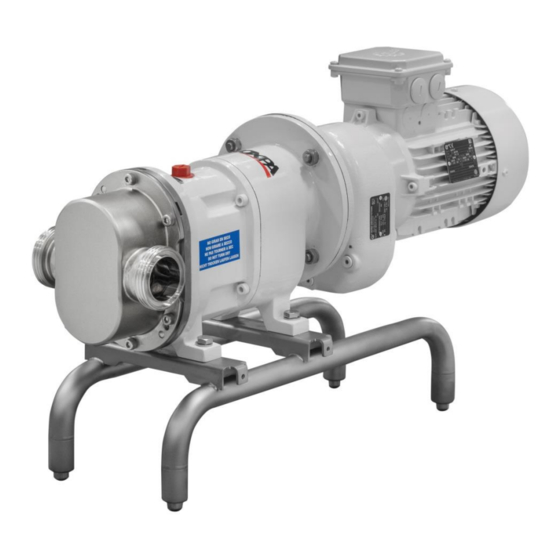
- Page 1 INSTALLATION, SERVICE AND MAINTENANCE INSTRUCTIONS LOBE PUMP Original Manual 01.520.30.07EN (0) 2019/04...
- Page 2 EN 60204-1:2006+A1:2009 In compliance with regulation (EC) nº 1935/2004 on Materials and articles intended to come into contact with food The technical file has been prepared by the signer of this document in INOXPA David Reyero Brunet Technical Officer Manager...
-
Page 3: Table Of Contents
1. Table of Contents 1. Table of Contents 2. Generalities 2.1. Instructions manual ............................ 4 2.2. Compliance with the instructions ........................ 4 2.3. Warranty ..............................4 3. Safety 3.1. Warningy symbols ............................5 3.2. General safety instructions ......................... 5 4. General Information 4.1. -
Page 4: Generalities
Risk to the environment due to the type of substances released. 2.3. WARRANTY Any warranty will be void immediately and lawfully and, additionally, INOXPA will be compensated for any civil liability claims submitted by third parties, in the following cases: ... -
Page 5: Safety
Electric hazard Important instruction to prevent damage to the equipment and its functions ATTENTION 3.2. GENERAL SAFETY INSTRUCTIONS Read the instruction manual carefully before installing and starting the agitator. Contact INOXPA in case of doubt. 3.2.1. During the installation Technical Specifications chapter 9 should always be observed. - Page 6 ALWAYS disconnect the electrical power to the pump prior to carrying out any maintenance. Remove the fuses and disconnect the cables from the motor’s terminals. All electrical work must be carried out by authorised personnel. INOXPA S.A.U. · 01.520.30.07EN · (0) 2019/04...
-
Page 7: General Information
4.3. APPLICATION The main advantage of the INOXPA TLS lobe pump is its capacity to pump a great variety of viscous liquids, from 1 mPa.s up to 100.000 mPa.s. Furthermore, it is capable of pumping liquid products that require very careful handling and liquids that contain soft solids thus causing only a minimum degradation of same. - Page 8 General Information ATTENTION Misuse of the pump or its use beyond the operating limits may be dangerous or cause permanent damage the equipment INOXPA S.A.U. · 01.520.30.07EN · (0) 2019/04...
-
Page 9: Installation
5. Installation 5.1. RECEPTION OF THE PUMP INOXPA will not be liable for any deterioration of the material due to transport or unpacking. Visually check that the packaging has not been damaged. The following documentation is included with the pump: ... -
Page 10: Transport And Storage
Install the pump so that it can be properly ventilated. If the pump is installed outdoors, it must be sheltered under a roof. Its location must allow for easy access during any inspection or maintenance tasks. INOXPA S.A.U. · 01.520.30.07EN · (0) 2019/04... -
Page 11: Pipes
Start and stop the pump motor momentarily. Make sure that the pump rotates in the correctly direction of rotation. ATTENTION ALWAYS check the direction of rotation of the motor with liquid inside the pump. INOXPA S.A.U. · 01.520.30.07EN · (0) 2019/04... -
Page 12: Start-Up
Prior to starting the pump, carefully read the instructions in chapter Installation. Carefully read chapter 9. Technical Specifications. INOXPA will not be liable for improper use of the equipment. NEVER touch the pump or the lines if hot liquids are being pumped. 6.1. CHECKS BEFORE STARTING THE PUMP ... - Page 13 The end user must adjust the valve to the correct pressure. When an overflow valve or a pressure bypass does not operate properly, the pump must immediately be removed from service for repair. INOXPA S.A.U. · 01.520.30.07EN · (0) 2019/04...
-
Page 14: Troubleshooting
The attached table lists solutions to problems that may arise while operating the pump. It is assumed that the pump has been properly installed and that is has been selected correctly for the specific application. Contact INOXPA if technical assistance is required. Motor overload The pump flow or pressure is insufficient. -
Page 15: Maintenance
(l) TLS 1 TLS 2 TLS 3 8.4. STORAGE Before storing the pump it should be completely drained. Prevent as far as possible exposing the parts to excessively humid environments. INOXPA S.A.U. · 01.520.30.07EN · (0) 2019/04... -
Page 16: Cleaning
Maximum conditions during the SIP process with steam or overheated water: a) Max. temperature: 140°C / 284°F b) Max. time: 30 min c) Cooling: sterile air or inert gas d) Materials: EPDM/PTFE (recommended) FPM/NBR (not recommended) INOXPA S.A.U. · 01.520.30.07EN · (0) 2019/04... -
Page 17: Disassembly And Assembly Of The Pump
Incorrect assembly or disassembly may cause damage in the pump’s operation and lead to high repair costs and a long period of down time. INOXPA is not responsible for accidents or damages cause by a failure to comply with the instructions in this manual. - Page 18 Once the pump casing is assembled, the Allen screws (51) must be tightened (crosswise). 8.6.1.1. Markings and lobes positions 8.6.1.2. TLS pump clearances and tolerances INOXPA S.A.U. · 01.520.30.07EN · (0) 2019/04...
- Page 19 Position the stationary part (08A) of the mechanical seal in its location in the seal cover. Fit the back seal cover (09A) in the seal cover (09) and tighten the screws (50B) on the support 1 or the screws (51F) on the supports 2 and 3. INOXPA S.A.U. · 01.520.30.07EN · (0) 2019/04...
- Page 20 Empty the oil from the support, remove the oil plug (85) and the bleed-emptying plug (87). INOXPA S.A.U. · 01.520.30.07EN · (0) 2019/04...
- Page 21 Fit the lantern unit and the drive in the support, and on doing so, take care of the centring pins (56A). Fit the Allen screws (51B). Fill the oil sump with the recommended oil type; see oiling instructions. INOXPA S.A.U. · 01.520.30.07EN · (0) 2019/04...
- Page 22 Check if the flector (40) is in good condition. Change the drive. Once the drive is fitted, fill the oil sump with the oil type recommended in the oiling instructions. INOXPA S.A.U. · 01.520.30.07EN · (0) 2019/04...
-
Page 23: Technical Specifications
Maximum temperature for continuous application due to EPDM gaskets and standard lobe rotor clearances. Consult for higher temperatures. The maximum viscosity allowed will depend on the nature of the liquid and the sliding speed of the seal faces. Consult INOXPA should the viscosity be still greater. INOXPA S.A.U. · 01.520.30.07EN · (0) 2019/04... -
Page 24: Size Of Particle
TLS 3-50 38,5 TLS 3-80 38,5 9.4. TIGHTENING TORQUES Pump size lbf·ft 9.5. WEIGHTS Pump size 0,55 TLS 1-25 0,75 0,75 TLS 1-40 TLS 2-40 TLS 2-50 2,2 / 3 TLS 3-50 TLS 3-80 INOXPA S.A.U. · 01.520.30.07EN · (0) 2019/04... -
Page 25: Dimensions
Technical Specifications 9.7. DIMENSIONS Pump size 0,55 TLS 1-25 0,75 0,75 TLS 1-40 TLS 2-40 TLS 2-50 2,2 / 3 TLS 3-50 1010 TLS 3-80 1035 1035 INOXPA S.A.U. · 01.520.30.07EN · (0) 2019/04... -
Page 26: Exploded Drawing
Technical Specifications 9.8. EXPLODED DRAWING INOXPA S.A.U. · 01.520.30.07EN · (0) 2019/04... -
Page 27: Parts List
Safety washer Steel Conical tightening ring Steel Elastic ring Steel Ball bearings Steel Needle bearings Steel O-ring EPDM Joint EPDM O-ring O-ring EPDM Oil plug Plastic Peephole Plastic Bleeder Plastic Lip seal Drive INOXPA S.A.U. · 01.520.30.07EN · (0) 2019/04... -
Page 28: Tls Shroud
Technical Specifications 9.10. TLS SHROUD Description Position Quantity Material Shroud with joint AISI 304 Hexagonal flange screw INOXPA S.A.U. · 01.520.30.07EN · (0) 2019/04... -
Page 29: Lip Seal
Material TLS 1 TLS 2 TLS 3 Lip seal Back seal cover AISI 316L Lip seal cover AISI 316L Shaft sleeve AISI 316L Shaft sleeve AISI 316L Countersink screw Allen screw O-ring EPDM INOXPA S.A.U. · 01.520.30.07EN · (0) 2019/04... - Page 30 NOTES ________________________________________________________________________________ ________________________________________________________________________________ ________________________________________________________________________________ ________________________________________________________________________________ ________________________________________________________________________________ ________________________________________________________________________________ ________________________________________________________________________________ ________________________________________________________________________________ ________________________________________________________________________________ ________________________________________________________________________________ ________________________________________________________________________________ ________________________________________________________________________________ ________________________________________________________________________________ ________________________________________________________________________________ ________________________________________________________________________________ ________________________________________________________________________________ ________________________________________________________________________________ ________________________________________________________________________________ ________________________________________________________________________________ ________________________________________________________________________________ ________________________________________________________________________________ ________________________________________________________________________________ ________________________________________________________________________________ ________________________________________________________________________________ ________________________________________________________________________________ ________________________________________________________________________________ ________________________________________________________________________________ ________________________________________________________________________________ ________________________________________________________________________________ ________________________________________________________________________________...
- Page 31 NOTES ________________________________________________________________________________________ ________________________________________________________________________________________ ________________________________________________________________________________________ ________________________________________________________________________________________ ________________________________________________________________________________________ ________________________________________________________________________________________ ________________________________________________________________________________________ ________________________________________________________________________________________ ________________________________________________________________________________________ ________________________________________________________________________________________ ________________________________________________________________________________________ ________________________________________________________________________________________ ________________________________________________________________________________________ ________________________________________________________________________________________ ________________________________________________________________________________________ ________________________________________________________________________________________ ________________________________________________________________________________________ ________________________________________________________________________________________ ________________________________________________________________________________________ ________________________________________________________________________________________ ________________________________________________________________________________________ ________________________________________________________________________________________ ________________________________________________________________________________________ ________________________________________________________________________________________ ________________________________________________________________________________________ ________________________________________________________________________________________ ________________________________________________________________________________________ ________________________________________________________________________________________ ________________________________________________________________________________________ ________________________________________________________________________________________ ________________________________________________________________________________________...
- Page 32 How to contact INOXPA S.A.U.: Contact details for all countries are Continually updated on our website Please visit www.inoxpa.com to access the information. INOXPA S.A.U. Telers, 60 – 17820 – Banyoles – Spain Tel.: +34 972 575 200 – Fax.: +34 972 575 502...
Need help?
Do you have a question about the TLS Series and is the answer not in the manual?
Questions and answers