Table of Contents
Advertisement
Quick Links
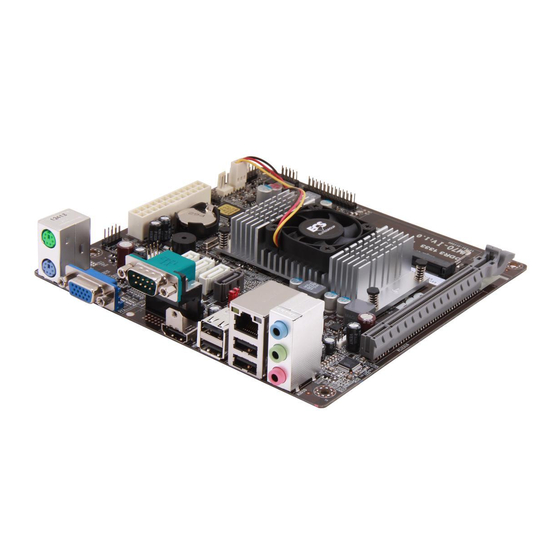
TECHNICAL MANUAL
Of
Intel Celeron 847/807 + Intel NM70 Chipset
Based Mini-ITX M/B
NO. G03-NC9R-F
Revision: 1.0
Release date: January 28, 2013
Trademark:
* Specifications and Information contained in this documentation are furnished for information use only, and are
subject to change at any time without notice, and should not be construed as a commitment by manufacturer.
Advertisement
Table of Contents


Need help?
Do you have a question about the Celeron 847 and is the answer not in the manual?
Questions and answers