Table of Contents
Advertisement
Quick Links
TECHNICAL MANUAL
Of
Intel Celeron 847 + Intel NM70 Chipset
Based Mini-ITX M/B
NO. G03-NC9Q-F
Revision: 1.0
Release date: March 26, 2013
Trademark:
* Specifications and Information contained in this documentation are furnished for information use only, and are
subject to change at any time without notice, and should not be construed as a commitment by manufacturer.
Advertisement
Table of Contents

Related Manuals for Intel Celeron 847


Summary of Contents for Intel Celeron 847
- Page 1 TECHNICAL MANUAL Intel Celeron 847 + Intel NM70 Chipset Based Mini-ITX M/B NO. G03-NC9Q-F Revision: 1.0 Release date: March 26, 2013 Trademark: * Specifications and Information contained in this documentation are furnished for information use only, and are subject to change at any time without notice, and should not be construed as a commitment by manufacturer.
- Page 2 Environmental Protection Announcement Do not dispose this electronic device into the trash while discarding. To minimize pollution and ensure environment protection of mother earth, please recycle.
-
Page 3: Table Of Contents
TABLE OF CONTENT ENVIRONMENTAL SAFETY INSTRUCTION................iii USER’S NOTICE ........................iv MANUAL REVISION INFORMATION ..................iv ITEM CHECKLIST ........................iv CHAPTER 1 INTRODUCTION OF THE MOTHERBOARD FEATURE OF MOTHERBOARD................1 SPECIFICATION ......................2 LAYOUT DIAGRAM....................3 CHAPTER 2 HARDWARE INSTALLATION JUMPER SETTING ..................... -
Page 4: Environmental Safety Instruction
Environmental Safety Instruction Avoid the dusty, humidity and temperature extremes. Do not place the product in any area where it may become wet. 0 to 60 centigrade is the suitable temperature. (The figure comes from the request of the main chipset) Generally speaking, dramatic changes in temperature may lead to contact malfunction and crackles due to constant thermal expansion and contraction from the welding spots’... -
Page 5: User's Notice
USER’S NOTICE COPYRIGHT OF THIS MANUAL BELONGS TO THE MANUFACTURER. NO PART OF THIS MANUAL, INCLUDING THE PRODUCTS AND SOFTWARE DESCRIBED IN IT MAY BE REPRODUCED, TRANSMITTED OR TRANSLATED INTO ANY LANGUAGE IN ANY FORM OR BY ANY MEANS WITHOUT WRITTEN PERMISSION OF THE MANUFACTURER. -
Page 6: Chapter 1 Introduction Of The Motherboard Feature Of Motherboard
Introduction of the Motherboard Feature of Motherboard ® ® Intel Celeron 847 processor+ Intel NM70 express chipset Support 2 * DDRIII SO-DIMM 1066/1333 MHz up to 16GB and dual channel function Support PCI Express 2.0 x16 slot and Mini-PCIE/mSATA slot Integrated with two 24-bit dual channel LVDS headers Support 2 * Serial ATAII (3Gb/s) &... -
Page 7: Specification
1-2 Specification Spec Description Design 6-layer Mini-ITX form factor ; PCB size: 17.0x17.0cm ® Intel Celeron 847 Dual Core Processor (1.1GHz) Embedded CPU ® Intel NM70 Express Chipset Chipset DDRIII SO-DIMM slot x2 Support DDRIII 1066/1333 MHz DDRIII SO-DIMM Memory Slot... -
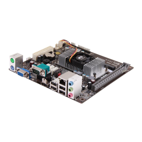
Page 8: Layout Diagram
4-Pin ATX12V connector x 1 SATAII Connector x2 SATAIII Connector x1 Front panel audio header x1 LANLED header x1 CIR header x1 GPIO header x1 PS2 KB&MS header x1 Front panel header x1 9-Pin USB 2.0 header x1 (support two expansion USB 2.0 ports) 4-Pin USB 2.0 header x1 (support one expansion USB 2.0 ports) - Page 9 LVDS1 Header Mini-PCIE/mSATA Slot GPIO DVI-D Port Header over VGA Port ATX12V Power connector Intel NM70 Chipset CIR Header DDRIII SODIMM Slot x 2 LAN Activity (DDRIII 1066/1333) USB 2.0 Ports LED Header Intel Celeron 847 CPU RJ-45 Port over USB 2.0 Ports...
- Page 10 Motherboard Jumper Position JBAT COPEN...
- Page 11 Connectors Connector Name ATXPWR ATX Power Connector ATX12V1 ATX 12V Power Connector SATA1 Serial ATAIII Connectors SATA2/SATA3 Serial ATAII Connectors HDMI High-Definition Multimedia Interface USB3 USB 3.0 Port Connector x 2 COM1_2 Serial Port Connector x2 VGA_DVI-D(Top) DVI-D Port Connector VGA_DVI-D (Bottom) Video Graphic Attach Connector USB2...
- Page 12 Jumper Jumper Name Description JBAT CMOS RAM Clear Function Setting 3-pin Block Mini_ CARD Power VCC 3.3V /3.3 VSB Select 3-pin Block PCI-E X16/X8 Mode Select 2-Pin Block COM2 Pin9 Function Select 6-pin Block ME_Update Function Select 2-Pin Block LVDS1 Backlight 12V/5V Select 3-pin Block LVDS1 PVCC 5V/3.3V Select 3-pin Block...
-
Page 13: Jumper Setting
Chapter 2 Hardware Installation 2-1 Jumper Setting (1) JBAT (3-pin): Clear CMOS Function Setting JBAT 1-2 Short: Normal; 2-3 Short: Clear CMOS CMOS Clear Setting (2) JP1 (3-pin): Mini_CARD Power VCC 3.3V/ 3.3VSB Select 1-2 closed: MINI_CARD Power VCC=3.3V; 2-3 closed: MINI_CARD Power VCC=3.3VSB... - Page 14 (3) JP2 (2-pin): PCI-E 2.0 Slot x16/x8 Mode Select 1-2 Open: PCI-E 2.0 x16 1-2 Closed: PCI-E 2.0 (4) JP3 (6-pin): COM2 Pin9 Function Select 1-2 closed: RI 3-4 closed : +12V 5-6 closed : +5V...
- Page 15 (5) JP4 (2-pin): ME_Update Function Select 1-2 Open: Normal; 1-2 Closed: When updating ME; (6) JP5 (3-pin):LVDS1 Backlight 12V/5V Select 1-2 closed: LVDS1 Backlight = 12 V; 2-3 closed: LVDS1 Backlight = 5 V;...
- Page 16 (7) JP6 (3-pin): LVDS1 PVCC 5V/3.3V Select 1-2 closed: LVDS1 PVCC= 5V; 2-3 closed: LVDS1 PVCC=3.3V (8) JP7 (3-pin):LVDS2 Backlight 12V/5V Select 1-2 closed: LVDS2 Backlight = 12 V; 2-3 closed: LVDS2 Backlight = 5 V;...
- Page 17 (9) JP8 (3-pin): LVDS2 PVCC 5V/3.3V Select 1-2 closed: LVDS2 PVCC= 5V; 2-3 closed: LVDS2 PVCC=3.3V (10)COPEN (2-pin): Case Open Message Display Function Select COPEN 1-2 Open: Normal; COPEN 1-2 closed : Case Open Pin 1-2 shorted: Case open display function enabled. Use needs to enter BIOS and enable ‘Case Open Detect’...
-
Page 18: Connectors And Headers
Connectors and Headers 2-2-1 Connectors (1) Rear Panel Connectors RJ-45 LAN Port DVI-D Port USB 3.0 Ports Serial Port Line-IN/SPDIF-OUT Line-OUT MIC-IN VGA Port HDMI Port Serial Port USB 2.0 Ports (2) ATXPWR (24-pin block): Power Connector PIN ROW1 ROW2 +3.3V +3.3V +3.3V... - Page 19 (3) ATX12V (4-pin block): ATX12V Type Power Connector Pin1 Pin No. Definition +12V +12V (4) SATA1: Serial-ATAIII Port connector These connectors are high-speed SATAIII ports that support 6 GB/s transfer rate. Pin No. Defnition...
-
Page 20: Headers
(5) SATA2/SATA3:SATAII Port connector These connectors are high-speed SATAII ports that support 3 GB/s transfer rate. Pin No. Defnition 2-2-2 Headers (1) FP_AUDIO (9-pin): Line-Out, MIC-In Header This header connects to Front Panel Line-out, MIC-In connector with cable. FP_AUDIO Pin 1 Line-Out, MIC Header... - Page 21 (2) LAN_LED (2-pin): LANLED Activity Header Pin1 LED+ LED- (3) CIR_CON (7-Pin): CIR Header Pin 1...
- Page 22 (4) GPIO_CON (10-pin): GPIO Header Pin 1 (5) PS2_CON (6-pin): PS/2 Keyboard & Mouse Header Pin1...
- Page 23 (6) JW-FP (9-pin): Front Panel Header Pin 1 (7) F_USB1 (9-pin): USB 2.0 Port Header Pin 1...
- Page 24 (8) F_USB2 (4-pin): USB 2.0 Port Header Pin 1 (9) INVERTER1/2 (8-Pin): LVDS Inverter Header Pin No. Definition Backlight Enable Backlight Duty Backlight Power Backlight Power Pin 1 Backlight+ SW Backlight- SW INVERTER...
- Page 25 (10) LVDS1/LVDS2 (30-pin): 24-bit dual channel LVDS Header Pin 1 Pin 2 Pin NO. Pin Define Pin NO. Pin Define Pin 1 LVDSB_DATAN3 Pin 2 LVDSB_DATAP3 Pin 3 LVDS_CLKBN Pin 4 LVDS_CLKBP Pin 5 LVDSB_DATAN2 Pin 6 LVDSB_DATAP2 Pin 7 LVDSB_DATAN1 Pin 8 LVDSB_DATAP1...
- Page 26 (11) CPUFAN1 (4-pin)/SYSFAN1 (4-pin)/SYSFAN2 (4-pin): FAN Speed Headers Pin1 CPUFAN/SYSFAN1/SYSFAN...
-
Page 27: Chapter 3 Introducing Bios
Chapter 3 Introducing BIOS Notice! The BIOS options in this manual are for reference only. Different configurations may lead to difference in BIOS screen and BIOS screens in manuals are usually the first BIOS version when the board is released and may be different from your purchased motherboard. Users are welcome to download the latest BIOS version form our official website. -
Page 28: Bios Menu Screen
BIOS Menu Screen The following diagram show a general BIOS menu screen: Menu Bar General Help Items Current Setting Value Menu Items Function Keys BIOS Menu Screen Function Keys In the above BIOS Setup main menu of, you can see several options. We will explain these options step by step in the following pages of this chapter, but let us first see a short description of the function keys you may use here: Press←→... -
Page 29: Getting Help
Press <Enter> to select. Press <+>/<–> keys when you want to modify the BIOS parameters for the active option. [F1]: General help. [F2]: Previous value. [F3]: Optimized defaults. [F4]: Save & Reset. Press <Esc> to quit the BIOS Setup. Getting Help Main Menu The on-line description of the highlighted setup function is displayed at the top right corner the screen. -
Page 30: Main Menu
Main Menu Main menu screen includes some basic system information. Highlight the item and then use the <+> or <-> and numerical keyboard keys to select the value you want in each item. System Date Set the date. Please use [Tab] to switch between data elements. System Time Set the time. -
Page 31: Advanced Menu
3-7 Advanced Menu ERP Function The optional settings are: [Auto];[Disabled]; Use this item to enable or disable ERP function for this board. This item should be set as [Disabled] if you wish to have Active All Wakeup Function(Include PS2, RTC, AC Power Loss, etc…). - Page 32 This item should be set as [Disabled] for Windows XP. Execute Disable Bit The optional settings are: [Disabled]; [Enabled]. Intel Virtualization Technology The optional settings: [Enabled]; [Disabled]. When set as [Enabled], a VMM can utilize the additional hardware capabilities provided by Vanderpool Technology.
- Page 33 The optional settings are: [Disabled]; [Enabled]. Use this item to turn on/off prefetching of adjacent cache lines. ► SATA Configuration Press [Enter] to make settings for the following sub-items: SATA Controller(s) Use this item to enable or disable SATA device. The optional settings: [Enabled];...
- Page 34 EHCI Hand-off This is a workaround for OSes without EHCI hand-off support. The EHCI ownership change should be claimed by EHCI driver. The optional settings are: [Disabled]; [Enabled]. USB hardware delay and time-out: USB Transfer time-out Use this item to set the time-out value for control, bulk, and interrupt transfers. The optional settings are: [1 sec];...
- Page 35 CPU PPM Configuration: EIST The optional settings: [Enabled]; [Disabled]. Use this item to enable or disable Intel SpeedStep. CPU C3 Report The optional settings: [Enabled]; [Disabled]. Use this item to enable or disable CPU C3 (ACPI C2) report to OS.
- Page 36 The optional settings: [Enabled]; [Disabled]. Use this item to enable or disable CPU C6 (ACPI C3) report to OS. ► SmartFan Configuration Press [Enter] to make settings for SmartFan Configuration: SmartFan Configuration: CPUFAN 3/4 Pin Fan Select/ SYSFAN1 3/4 Pin Fan Select / SYSFAN2 3/4 Pin Fan Select The optional settings are: [3 Pin];[4 Pin].
-
Page 37: Chipset Menu
3-8 Chipset Menu ► PCH-IO Configuration Press [Enter] to make settings for the following sub-items: ► USB Configuration Press [Enter] to further setting USB device configuration. USB 3.0 Controller The optional settings are: [Enabled]; [Disabled]. EHCI1/ EHCI2 Use this item to enable or disable USB EHCI (USB 2.0) support. One EHCI controller must always be enabled. - Page 38 The optional settings are: [Disabled]; [Enabled]. PCIe Speed The optional settings are: [Auto]; [Gen1]; [Gen2]. Azalia Use this item to control detection of the Azalia device. The optional settings are: [Disabled]; [Enabled];[Auto]. [Disabled]: Azalia will be unconditionally disabled; [Enabled]: Azalia will be unconditionally enabled; [Auto]: Azalia will be enabled if present, disabled otherwise.
- Page 39 Aperture Size The optional settings are: [128MB]; [256MB]; [512MB]. DVMT Pre-Allocated Use this item to select DVMT 5.0 pre-allocated (fixed) graphics memory size used by the internal graphics device. The optional settings are: [32M]; [64M]; [128M]; [256M]; [512M]; [1024M]. DVMT Total Gfx Mem Use this item to select DVMT 5.0 total graphics memory size used by the internal graphics device.
- Page 40 [1280 x 1024]; [1400 x 1050]; [1600 x 1200]; [1366 x 768]; [1680 x 1050]; [1920 x 1200]; [1440 x 900]; [1600 x 900]; [1024 x 600]; [1280 x 600];[1920 x 1080]; [2048 x 1536]. Backlight Control The optional settings are: [PWM Inverted]; [PWM Normal]. LVDS1 Panel Color Depth The optional settings are: [18 Bit];...
-
Page 41: Boot Menu
not show on the screen when ‘DIMM Profile’ is set as: [Custom Profile]. The optional settings are [Auto]; [1067]; [1333]. MMode Support The optional settings are: [Auto]; [1N Mode]; [2N Mode]. Memory Remap Use this item to enable or disable memory remap above 4G. The optional settings are: [Enabled];... - Page 42 Quiet Boot The optional settings are: [Enabled]; [Disabled]. Fast Boot The optional settings are: [Enabled]; [Disabled]. ► CSM parameters Press [Enter] to make settings for the following sub-items: Boot option filter This option controls what device system can boot to. The optional settings are: [UEFI and Legacy];...
-
Page 43: Security Menu
3-10 Security Menu Administrator Password This item allows user to set administrator password. User Password This item allows user to set user password. Secure Boot To secure boot flow control. Secure boot is possible only of system run in user mode. The optional settings are: [Enabled];... - Page 44 When set as [Custom], the following sub-items will appear onscreen for user to set customized settings: ► Image Execution Policy Press [Enter] to make settings for the following sub-items: Internal FV Image Execution Policy per device path on Security Violation. Only user logged with Administrator password can exercise query user policy setting.
- Page 45 selected file system’ root. ▶ Delete the PK Use this item to delete the Variable. Key Exchange Key Database (KEK) ▶ Set KEK from File Use this item to launch the file browser to set EFI variable from the file. The file data must be formatted as EFI variable with Timebased Authenticated Header.
-
Page 46: Save & Exit Menu
▶ Get DBX to File Use this item to store Secure Variable to a file with a matching name in selected file system’ root. ▶ Delete the DBX Use this item to delete the Variable. ▶ Append an entry to DBX Use this item to launch the file browser to set Append new Signature Database from the file. - Page 47 Discard Changes and Reset This item allows user to reset the system without saving any changes. Restore Defaults Use this item to restore /load default values for all the setup options. Save as User Defaults Use this item to save the changes done so far as user defaults. Restore User Defaults Use this item to restore defaults to all the setup options.
Need help?
Do you have a question about the Celeron 847 and is the answer not in the manual?
Questions and answers