Advertisement
Quick Links
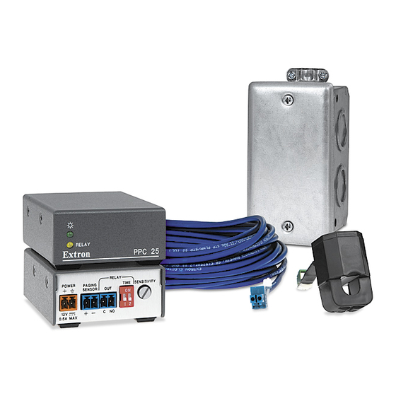
PPC 25 Installation Instructions
PPC 25 Overview
The PPC 25 consists of the Priority Page
Controller and Priority Page Sensor.
Together they mute classroom audio for
the duration of an announcement that is
made over a Public Address (PA) system.
The Sensor connects to a PA speaker
lead and detects current flow when a
PA announcement is initiated.
The Sensor signal triggers the PPC 25
controller's output relay to close. This
relay closure can connect to a PoleVault
switcher, a Mini Power Amplifier (MPA),
a MediaLink
™
Controller (MLC), or any
device with a contact closure type of
mute control or a configurable digital
input.
The output relay remains closed until the PA
announcement ends. It then opens, dropping
the mute signal and restoring the classroom audio.
For a PoleVault System, the output relay should connect only to the PVS 204SA and not the MLC. This requires no
software configuration.
If the Output Relay is connected to an MLC digital input, use Global Configurator software to configure the input
port, and set the monitoring conditions and actions to drive the desired mute function on the classroom audio device.
The PPC 25 Controller and Sensor are rated for use in plenum environments (any area utilized for air handling,
including areas above suspended ceilings and below raised floors). The PPC 25 Sensor assembly must be installed
in a UL-compliant junction box with a cover to meet the plenum rating requirement.
The PPC 25 works with traditional 25V or 70V and 4/8 ohm PA systems. It was not designed
for, and may not work properly with, systems using digital clocks and two-way intercoms.
Front and Rear Views of the PPC 25 Controller
a
Power-on LED — green when power is on
b
RELAY LED — amber when output relay is closed
c
POWER receptacle — 12 VDC, 33 mA. The unit does not ship
with a power supply. Power may be shared with another device.
Polarity must be observed.
d
PAGING SENSOR connector — for the Priority Page Sensor that
is located near a PA system speaker
e
RELAY OUT connector — connects to an amplifier or switcher
that has a contact closure type of mute control input, or to an MLC
device with a digital input. When a PA system announcement is
initiated, the output relay closes and remains closed for the duration of the announcement. The closed output
relay triggers the classroom audio mute function. When integrating the PPC 25 into a PoleVault System,
connect the output relay to the PVS 204SA Mute and Ground pins only (see diagram on page 2).
f
TIME switch — sets how long the output relay will remain closed after a PA announcement has ended. A
short time delay is necessary so that if the PA system announcer pauses briefly during the announcement, the
classroom audio is not restored prematurely. The 2-position DIP switch provides the following time settings:
TIME
ON
= 2.0 sec (default)
1 2
g
SENSITIVITY adjustment — sets the sensitivity level for the signal arriving from the Priority
Page Sensor. The final setting depends on the type of paging system and the number of wire
loops on the Sensor (see page 2). Rotate clockwise to increase sensitivity and counterclockwise
to decrease sensitivity.
Admin Building
To Classroom
Paging Speakers
™
Paging System
A Typical PPC 25 Installation
= 4.0 sec
= 6.0 sec
PPC 25 Priority Page Sensor • Installation Instructions
Classroom
PPC 25
Ceiling Mounted
Priority
Paging Speaker
Page
Sensor
Extron
PVS 204SA
Twisted Pair
Switcher
1A
I
N
P
U
T
W ER
S
PO
1B
V
12
MA
X
3A
Y
ITI
VIT
NS
SE
Y
Extron
DE
LA
ON
LA
Y
RE
1
2
GI NG
W ER
PA
PO
NO
C
V
X
PPC 25
12
A
MA
0.2
Relay Output
Priority Page
Controller
1
2
RELAY
POWER
PAGING
SENSOR
12V
0.5A MAX
3
4
= 8.0 sec
Extron
SI 26
Surface Mount
Speakers
UT
S
m s
TP
Oh
D OU
4/8
IF IE
PL
AM
R
ND
L
T GR
OU
T
!
L
VO
NO
OR
TS
DC
DO
OR
SH
OU
TPU
C/ IR
T
KE
R
V
17T
O
SP
EA
-2 32
ML
12
LIS
TED
DE
IR
DIO
/VI
TU
S
RS
Rx
V
TE
AU
PA
RA
Tx
10
L/ MU
US
AP
VO
®
C
B
A
B
X IN
RG
X/ MI
O
AU
U
Remote
O
T
VI DE
P
3A
U
T
S
2A
B
RG
Vol/Mute
VI DE
O
3B
2B
Control
PPC 25
RELAY
TIME
SENSITIVITY
OUT
ON
1 2
C NO
5
6
7
68-1437-01
Rev F
04 08
1
Advertisement

Related Manuals for Extron electronics Priority Page Controller PPC 25


Summary of Contents for Extron electronics Priority Page Controller PPC 25
- Page 1 PVS 204SA Mute and Ground pins only (see diagram on page 2). TIME switch — sets how long the output relay will remain closed after a PA announcement has ended. A short time delay is necessary so that if the PA system announcer pauses briefly during the announcement, the classroom audio is not restored prematurely.
-
Page 2: Installation Procedure
PPC 25 Installation Instructions, cont’d Installation Procedure Follow all local fire and safety code requirements for installation and anchoring. Install the PPC 25 Sensor in a UL-compliant junction box with a cover to meet plenum rating requirements. Open the top of the Priority Page Sensor. Loop either one of the speaker wire leads around the top (open) part of the Sensor, and connect it to the speaker as shown above.
Need help?
Do you have a question about the Priority Page Controller PPC 25 and is the answer not in the manual?
Questions and answers