Advertisement
Quick Links
Advertisement

Subscribe to Our Youtube Channel
Related Manuals for Malossi 5517526


Summary of Contents for Malossi 5517526
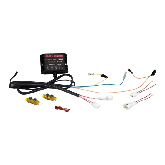
- Page 1 Art. 5517526 - 1 -...
- Page 2 Force Master 2 è l’innovativa centralina, programmata con 4 diverse mappature, per adattarsi perfettamente al vostro veicolo, qualunque sia la sua confi gurazione. Le mappature sono state eseguite al banco prova statico, simulando l’effettivo carico del motore come se fosse su strada. Questo ci ha permesso di avere una carburazione molto raffi...
-
Page 3: Dati Tecnici
- 4 programmes différents: • Courbe 0 : arbre à cames d’origine, pot d’échappement d’origine • Courbe 1 : arbre à cames d’origine, pot d’échappement Malossi avec DB killer • Courbe 2 : arbre à cames Malossi, pot d’échappement d’origine •... - Page 4 - Position the Force Master 2 CDI into the helmet holder or into the battery holder (Fig. 1) and run the wires to the engine, taking care that they will not be damaged. - Apply the splice, supplied in the Malossi kit, to the white/red wire that exits the TPS connector on the butterfl y housing (Fig. 2, part. 8).
- Page 5 - Á ce point là, connecter la cosse faston mâle aux câbles du véhicule en utilisant le raccord, comme indiqué dans la Fig. 6. - Suivre le fi l sortant de l’injection et individualisez le connecteur, en y connectant les 2 connecterus présent sur le boîtier Malossi (Fig.
- Page 6 ATTENZIONE: Qualora si voglia riportare il veicolo allo stato originale, sarà suffi ciente staccare i connettori della centralina e ricollegare i due connettori Malossi (Fig. 9). Taratura TPS (throttle position sensor) – Fig. 11 - Ruotare il trimmer “LOW” sulla freccia rossa.
- Page 7 - Ruotare il trimmer “HIGH” sulla freccia rossa. - Aprire completamente la manopola del gas. - Ruotare la chiave del veicolo su ON. - Attendere la completa accensione dei 3 led e il successivo spegnimento. - Ruotare la chiave del veicolo su OFF. - Ruotare il trimmer sullo zero.
- Page 8 Fig. 11 ATTENZIONE: (Fig. 11) se uno dei 3 trimmer è posizionato sulla freccia rossa non è possibile avviare il veicolo. ATTENTION: (Fig. 11) if one of the three trimmers is positioned on a red arrow then the vehicle will not start. ATTENTION: (Fig.
- Page 9 DIAGNOSTICA Sulla centralina sono presenti 3 led di diverso colore (Fig. 10): • ROSSO : indicazione avaria centralina. Se a veicolo acceso il led rosso si illumina signifi ca che c’è un’avaria. Le principali cause di avaria possono essere: 1. Tensione batteria troppo bassa o alta 2.
- Page 10 Les niveaux de programmation sont subdivisés dans les groupes suivants: • Courbe 0 : arbre à cames d’origine, pot d’échappement d’origine • Courbe 1 : arbre à cames d’origine, pot d’échappement Malossi avec DB killer • Courbe 2 : arbre à cames Malossi, pot d’échappement d’origine •...
- Page 11 To add fuel, turn the potentiometers clockwise. To subtrac fuel, turn the potentiometer counterclockwise. With the potentiometer pointed straight up at the zero mark (towards the Malossi logo), that is 0% adjustment. With the potentiometer pointed straight up at the “ - ” mark is –20%.
- Page 12 Con il potenziometro posizionato sul segno “ + ” si ha una regolazione di +20%. Regolando il potenziometro tra questi due punti si aggiungerà o sottrarrà una quantità di carburante proporzionale a quanto la tacca viene spostata dallo zero. With the potentiometer pointed straight up at the “ + ” mark is +20%. Adjusting the potentiometer between these points will result in adding or subtracting an amount of fuel proportional to how far the knob was moved from zero.
- Page 13 Regolazione Per selezionare la curva adatta, cominciare verifi cando che tutti e tre i potenziometri siano posizionati sullo zero. Procedere quindi selezionando la curva che corrisponde alla confi gurazione del proprio veicolo. Questo consentirà al veicolo di ottenere prestazioni migliori ad ogni RPM. Qualora la confi...
- Page 14 “contact” section on our Internet site (www.malossi.com). We thank you in advance for any comments and suggestions you may wish to send us. So goodbye from us all at Malossi, and please accept our compliments.
- Page 15 Decliniamo ogni responsabilità per l’uso improprio. The descriptions in this publication are not binding. Malossi reserves the right to make modifi cations, if it considers them necessary, and does not accept any responsibility for any typographic or printing errors. This publication replaces all previous publications referring to the updating matters contained therein.
- Page 16 Fig. 1 - 16 -...
- Page 17 Fig. 2 - 17 -...
- Page 18 Fig. 3 - 18 -...
- Page 19 Fig. 4 • NERO / BLU • ROSSO / NERO • BLACK / BLUE • RED / BLACK • NOIR / BLEU • ROUGE / NOIR • ARANCIONE / NERO • ROSA / BLU • ORANGE / BLACK • PINK / BLUE •...
- Page 20 Fig. 6 - 20 -...
- Page 21 Fig. 7 - 21 -...
- Page 22 Fig. 8 - 22 -...
- Page 23 Fig. 9 - 23 -...
- Page 24 Fig. 10 • CAVO BOBINA • COIL CABLE • CÂBLE BOBINE • LIBERO • FREE • LIBRE • INIETTORE • INJECTOR • INJECTEUR - 24 -...
Need help?
Do you have a question about the 5517526 and is the answer not in the manual?
Questions and answers