Table of Contents
Advertisement
Quick Links
Advertisement
Table of Contents

Related Manuals for RefPlus Guardian+ RC-A


Summary of Contents for RefPlus Guardian+ RC-A
- Page 1 PROGRAMMING MANUAL VERSION 1.4 OPTI-MIST PLUS ADIABATIC CONTROL RC-A...
- Page 2 pecificationS...
-
Page 3: Table Of Contents
able of ontentS INTERFACE KEY DESCRIPTIONS ..............................4 NAVIGATION PRINCIPLES ....................................OPERATION PRINCIPLE / SEQUENCE OF OPERATION ....................... 5 COOLING DEMAND ........................................SYSTEM SELECTION: PULSING VALVE ................................SYSTEM SELECTION: MODULATING PUMP ..............................STATUS AND PROGRAMMING MENU & SUB-MENUS DIAGRAM ................... 11 MENUS AND PARAMETERS ................................ -
Page 4: Interface Key Descriptions
nterface eScriptionS ALARM KEY Lets you access the Alarm menu (some controller models may have a bell icon) PROGRAMMING KEY Lets you access the Programming menu ( on some controller models) ESCAPE KEY Returns to the Status menu or the previous menu ( on some controller models) DOWN KEY Lets you navigate down through screens and menus or lets you change the value of a field... -
Page 5: Operation Principle / Sequence Of Operation
For the sake of simplicity, they are often called PV and MP, The system is controlled by the Guardian+ RC-A controller respectively, in this manual. Some parameters are only used (PLC) to ensure a fully automatized operation and to run the for one of these configurations. - Page 6 When using the Ladder method, when the cooling SYSTEM SPECS (SCALER) demand varies, the pulse length remains the same within predetermined cooling demand ranges (i.e. 0%-20%). When Demand: LOT HOT PER the cooling demand reaches the next range (i.e.20%-40%), 006-010/060s the pulse length then changes.
- Page 7 According to Graph 2 and Graph 4, if the cooling demand is RANGE MODE PROP MODE 60%, the pulse length will be either 28 or 34 seconds. If the outside temperature is 22 C or below, the pulse length will be 28 seconds (LOT).
- Page 8 temperature point (OutTempLW + OutTempLW band) is RANGE PROP equal to 27 C, where the longest pulses (HOT) will be applied, depending on the cooling demand (left column on Screen E). 18.5 The cooling demand is expressed in % as shown in Graph 1.
-
Page 9: System Selection: Modulating Pump
SYSTEM SPECIFICATIONS SYSTEM SPECS (LADDER) Demand: Pulse 0%-020% 006/060s PumpON when CD is: 010% 020%-040% 014/060s 040%-060% 023/060s OutTempLW: 22.0 060%-080% 032/060s OutTempLW band: 05.0 080%-100% 041/060s OutTempLW Mode: Prop 100% 050/060s Screen G Screen F SYSTEM SPECIFICATIONS SYSTEM SELECTION: MODULATING PUMP Water pump LOT HOT If Modulating Pump has been set as the system selection... - Page 10 MODE SET TO RANGE: According to Graph 8 and Graph 9, RANGE MODE PROP MODE if the cooling demand is 0%, the pump speed will be either 40 or 50%. If the outside temperature is 22 C or below, the pump speed will be 40% (LOT).
-
Page 11: Status And Programming Menu & Sub-Menus Diagram
ADIABATIC Pump. Pump valve. Air vent val. Pump: 079% Set new date 20/09/08 20072114 Drain valve. OT: 010.0 yy/mm/dd by REFPLUS VERS 1.4 Water treat. FT: 031.3 TEMPERATURE UNIT OFFSETS FACTORY SETUP MENU UNIT STATUS 00.0 ALARMS LOGGING RESET Outside temp: 010.0... -
Page 12: Menus And Parameters
B>USER SETUP to scroll the Programming menu and select G) VERSION INFO 2. Use 3. Press . The screen will display the software version installed on the controller. In this case, the version is 1.4 ADIABATIC 20072114 by REFPLUS VERS 1.4... -
Page 13: Status Menu (System Status & Run Hours)
STATUS MENU (SYSTEM STATUS & RUN HOURS) When the controller is powered ON, it shows screen 1 of the Status menu. The Status menu has 3 screens. Each one shows important information regarding the status of the controller and the adiabatic system, such as time and date, controller status (ON/OFF), operating time, etc. -
Page 14: Factory Reset Procedure
. The display will read: ENTER FACTORY PASSWORD 0000 The screen may prompt you to enter the factory password. Please contact RefPlus to obtain your factory password. 4. Press 5. Use to enter the factory password. Note: If password is not accepted, verify that date and time are set properly. - Page 15 FACTORY RESET This will factory reset the unit. Are you sure? Reset Press and then to carry out the factory reset.
-
Page 16: Setting Up Your Controller Using The Programming Menu
. The display will read: ENTER FACTORY PASSWORD 0000 The screen may prompt you to enter the factory password. Please contact RefPlus to obtain your factory password. 4. Press 5. Use to enter the factory password. Note: If password is not accepted, verify that date and time are set properly. -
Page 17: System Specifications
7. Use to select SYSTEM SPECIFICATIONS and then press to confirm your selection. The display will read: SYSTEM SPECIFICATIONS PLAN:01 System selection: Pulsing valve Control by: Fluid temperature P-LAN indicates the controller’s P-LAN address. 8. Press 9. Using , set the system selection, either Pulsing Valve or Modulating Pump. Pulsing Valve: This is the main and most common system selection. - Page 18 PumpON when CD is: A minimum cooling demand can be set to prevent the pump from cycling. The pump will only start if there is a demand from the unit (cooler or condenser) and if the minimum cooling demand (PumpON when CD) has been reached.
-
Page 19: Communication Settings
28. If the system is set to Pulsing valve and Ladder, the display will read: SYSTEM SPECS (LADDER) Demand: LOT HOT PER 0%-020% 006-010/060s 020%-040% 014-020/060s 040%-060% 023-030/060s 060%-080% 032-040/060s 080%-100% 041-050/060s 100% 050-060/060s 29. Press and use to adjust these parameters as desired. Refer to the Operation Principle on page 7 for more information on the Ladder method. -
Page 20: Digital Inputs
COMMUNICATION SETTINGS BMS address:001 Protocol:CAREL Local Baudrate: 19200 baud 36. Press 37. Use to enter the BMS address, the controller’s address in a supervisory system. Press to confirm. 38. Use to enter the BMS port communication protocol. Set CAREL Local for pCOWEB and BACNET cards; set MODBUS Slave for MODBUS card. - Page 21 48. Press and use to set Water Inlet switch if installed. RefPlus strongly recommends installing this switch. Refer to the section entitled WATER INLET LOW PRESSURE SWITCH (LPS) OR LOW LEVEL SWITCH (LLS) on page 49.
-
Page 22: Delays
56. Use to set Delay and press to confirm. 57. Press , the display will show the Digital Input B6 screen: Digital Input B6 Water pump disch. sw. Active if Status CLOSED OPEN Delay time= 03secs. Digital input B6 (Water pump discharge switch, B6): signal from a high-pressure switch reading the pump outlet. If the input is active, after the delay shown here, an alarm is raised and the system stops. -
Page 23: Features/Alarms Enable/Disable
Fact. pass. enab (factory password enabled time): Once the factory password is inserted, access to the factory menu is allowed. If the time set here elapses, you must re-insert the password to access to the factory menu. This parameter applies also for the service password. -
Page 24: Devices Run Hours (Reset And Store Settings)
83. Press to confirm your selection. 84. Use to set Ck. demineralizer to YES or NO. This allows the user to enable or disable the demineralizer service alarm. 85. Press to confirm your selection. 86. Press to return to the FACTORY SETUP MENU. The display will read: FACTORY SETUP MENU DELAYS FEATURES/ALARMS EN/DIS... -
Page 25: Alarms Logging Reset
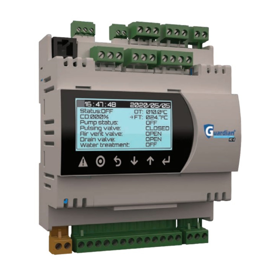
96. Use to select GENERAL STATUS. 97. Press to confirm your selection. The display will read: 16 : 47 : 48 2020/05/05 Status:OFF OT: 010.0 CD:000% FT: 024.7 Pump status: Pulsing valve: CLOSED Air vent valve: OPEN Drain valve: OPEN Water treatment: Displays the main screen without needing to exit the factory setup menu. -
Page 26: User Setup
2. USER SETUP 1. Enter the Programming menu by pressing . The display will read: PROGRAMMING MENU G>VERSION INFO A>UNIT ON/OFF B>USER SETUP 2. Use to scroll the Programming menu and select B) USER SETUP 3. Press . The display will read: ENTER USER PASSWORD 0000 The screen may prompt you to enter the user password. -
Page 27: Main Page Return Delay
10. Press , then use to enter the Setpoint value. A temperature range is defined for fluid or outside temperature, depending on the control type selected under the FACTORY menu on page 17. Refer to the Operation Principle on page 5. It is defined by two parameters: Temperature setpoint and Setpoint band. The adiabatic system will only operate within this range or above, and if the signal from the unit (cooler or condenser) has been received. -
Page 28: Offsets
The screen may prompt you to enter the service password. 4. Press the 5. Use to enter the Service password. Service password is 17. 6. Press to confirm the password. The display will read: OFFSETS 00.0 Outside temp: 010.0 00.0 Fluid temp: 024.7 7. -
Page 29: Service Alarms Settings
SERVICE ALARMS TIME: Pump oil: 02000hrs UV lights: 08000hrs Filter: 00600hrs Demineralizer: 00600hrs Minimum off: 072hrs NOTE: The Pump Oil parameter is only shown when the system uses a Modulating Pump. The controller saves the operating time for devices that are subject to maintenance (time since last maintenance was performed). -
Page 30: Clock
4. CLOCK This menu allows the user to set the present date and time. IMPORTANT: Always set the full date and time even when only modifying a single parameter. 1. Enter the Programming menu by pressing . The display will read: PROGRAMMING MENU G>VERSION INFO A>UNIT ON/OFF... -
Page 31: Alarm History
larm iStory This menu allows the user to view all triggered alarms (past or present). 1. Enter the Programming menu by pressing . The display will read: PROGRAMMING MENU G>VERSION INFO A>UNIT ON/OFF B>USER SETUP 2. Use to scroll the Programming menu and select E) ALARM HISTORY. 3. -
Page 32: Alarm System
larm yStem Once the controller detects a malfunction, it triggers the corresponding alarm. The control buzzer will sound and the red light will blink. By pressing the button (bell icon on some controller models), the user will access the alarms screens. The controller may prompt for the user password. -
Page 33: Switching The Adiabatic Control On/Off
on/off witcHing tHe Diabatic ontrol 1. Enter the Programming menu by pressing . The display will read: PROGRAMMING MENU G>VERSION INFO A>UNIT ON/OFF B>USER SETUP 2. Use to scroll the Programming menu and select A) UNIT ON/OFF. 3. Press The controller may prompt you to enter the User password. Enter password following instructions on page 26. The display will read: UNIT STATUS 000sec(s) - Page 34 CERTIFIED ISO-9001 IOM-GUARDIAN+ ADIABATIC CONTROLLER-EN-09/21-R0 RefPlus Inc. reserves the right to make any changes in the design or specifications of any product at any time without notice. USA & CANADA 1-888-816-2665 / refplus.com © Copyright 2021 by RefPlus Inc.
Need help?
Do you have a question about the Guardian+ RC-A and is the answer not in the manual?
Questions and answers