Table of Contents
Advertisement
Quick Links
Advertisement
Table of Contents

Subscribe to Our Youtube Channel
Related Manuals for RefPlus Guardian+


Summary of Contents for RefPlus Guardian+
- Page 1 QUICK START GUIDE Certified ISO-9001...
-
Page 2: Table Of Contents
Table of Contents SPECIFICATI0NS ............................................2 WIRING DIAGRAMS ....................................3 POWERED BY EXTERNAL SOURCE (PILOT DUTY) ....................................4 POWERED BY CONDENSING UNIT (LINE DUTY) ACCESSORIES ..............................................5 DIMENSIONS ..............................................6 COIL SENSOR LOCATION ..........................................6 NAVIGATION USING THE BASIC DISPLAY ..................................... 7 USER INTERFACE/CONTROLLER SETUP ...................................... -
Page 3: Powered By External Source (Pilot Duty)
Wiring Diagram - Powered by External Source (Pilot Duty) 240/1/60 USE COPPER CONDUCTOR ONLY DEFROST DELAY L2/N GREEN O-10V EMPTY BLUE BLUE ORANGE ORANGE EEV / YELLOW YELLOW RSV / KE2 SPORLAN BLACK BLACK TEMP6 WHITE BLACK AUX3 TEMP5 AUX2 TEMP4 AUX1 LEGEND... -
Page 4: Powered By Condensing Unit (Line Duty)
Wiring Diagram - Powered by Condensing Unit (Line Duty) USE COPPER CONDUCTORS ONLY TO CONDENSING UNIT DEFROST DELAY L2/N GREEN EMPTY O-10V BLUE ORANGE EEV / BLUE YELLOW SPORLAN ORANGE BLACK YELLOW RSV / KE2 WHITE BLACK BLACK TEMP6 AUX3 TEMP5 AUX2 USE COPPER SUPPLY WIRES... -
Page 5: Accessories
Accessories Remote Displays Part # Description 21232 Basic (Remote) Display w/ 15 ft. cable 21324 Snap track - 12” (305 mm) 21320 Combo Display (no accessories included) 21786 Combo Display - 25 ft. Cable (762 cm) 21320 Combo Display - Junction Box 21781 9V Rechargeable Battery for Combo Display Temperature Sensors... -
Page 6: Dimensions
After the sensors are mounted, they are routed back to the controller. If the wires must be extended,use 18 gauge twisted shielded pair. Maximum, combined length, for extension: 100 ft. Contact RefPlus Therm if planning to extend sensor wires beyond 100 ft. -
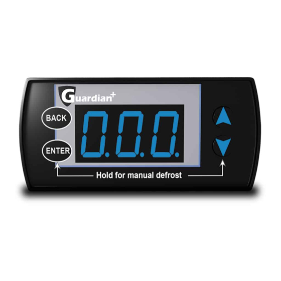
Page 7: Navigation Using The Basic Display
Navigation Using the Basic (Remote) Display Basic (Remote) Display User Interface Changing Setpoints Most Guardian+ controllers ship with the Basic Display. The display Pressing and holding the button will enter the Basic Set- ENTER allows service technicians to change the major setpoints. Setpoints points menu. -
Page 8: Menus And Parameters Basic Setpoints Menu
Menus & Parameters... - Page 9 Menus & Parameters...
-
Page 10: Types Of Control - First Time Setup Menu
Menus & Parameters... -
Page 11: Alarm Status Menu
Menus & Parameters... - Page 12 Menus & Parameters...
- Page 13 Menus & Parameters...
-
Page 14: Smart Access
(https://refplus.com/en/parts-services/) IOM-GUARDIAN-En-04/20-R2 ISO-9001 RefPlus Inc. reserves the right to make any changes in the design or USA & CANADA 1-888-816-2665 / refplus.com specifications of any product at any time without notice. 2777 Grande-Allée,Saint-Hubert, Québec,Canada,J4T 2R4 T 450 641-2665 F 450 641-4554...
Need help?
Do you have a question about the Guardian+ and is the answer not in the manual?
Questions and answers