Table of Contents
Advertisement
Quick Links
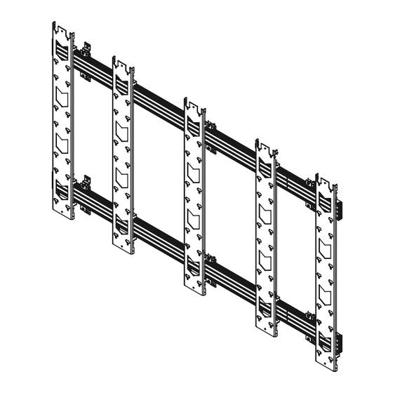
BT9340-Rm
DVLED Videowall WALL MOUNT
for rear mounted dvled cabinets
INSTALLATION GUIDE
SPECIFICATIONS
• Designed for rear mounted DVLED cabinets
• Open frame allows panel access for easy servicing
and maintenance
• Pre-assembly of major parts for quick and easy installation
• All mounting hardware included
• For indoor use only
www.btechavmounts.com
Advertisement
Table of Contents

Related Manuals for B-Tech BT9340-RM


Summary of Contents for B-Tech BT9340-RM
- Page 1 BT9340-Rm DVLED Videowall WALL MOUNT for rear mounted dvled cabinets INSTALLATION GUIDE SPECIFICATIONS • Designed for rear mounted DVLED cabinets • Open frame allows panel access for easy servicing and maintenance • Pre-assembly of major parts for quick and easy installation •...
- Page 2 It is recommended that periodic inspections of the product and its fixing points are made as frequently as possible (no more than 6 months apart) to ensure that safety is maintained. B-Tech AV Mounts recommends that a suitably qualified person is used for the removal of this product.
- Page 4 BT9340-rm PARTS LIST PLEASE KEEP THIS FOR FUTURE REFERENCE SPACERS Note: Images for reference only as sizes, parts and assembly may differ depending on installation type.
-
Page 5: Extension Kit
ITEM PART NAME WALL MOUNT ASSEMBLY ADJUSTABLE WALL PLATE (BT8390-WFK5) M8 x 50mm COACH SCREW No.10 WALL PLUG* RAIL ASSEMBLY MOUNTING RAIL* *If required. (For installing RAIL END CAP into brick/concrete walls) EXTENSION BARS INTERFACE ASSEMBLY INTERFACE PLATE SPACERS (VARIOUS LENGTHS) CABINET FIXING SCREW/BOBBIN TECHNICAL GUIDES Cabinet Fixing Screws/Bobbins... -
Page 6: Installation Instructions
INSTALLATION INSTRUCTIONS OPTIONAL EXTEND MOUNTING RAILS Connect item B1* together using item B3 and tighten grub screws, combining the rails securely. Repeat this procedure for all rails. *Note: Item B1 may be supplied in different lengths. Refer to item D1 for guidance on rail assembly. - Page 7 FIX MOUNTING RAILS TO THE WALL Keyhole mounting - Using a BT8390-WFK5 Adjustable Depth Wall Plate i. Use the installation drawing (item D1) to mark and drill the fixing holes for each item A1 assembled on item B1, starting with the bottom rail. ii.
- Page 8 iv. Refer to the installation drawing (item D1) to position and fix the remaining rails (item B1). Note: Add item B2 to the ends of items B1. ADJUST RAILS TO ALIGN v. Use a plumb line, spirit level and the depth adjustment screws on item A1 to align rails vertically and horizontally.
- Page 9 HOOK INTERFACE ARMS ONTO MOUNTING RAILS i. Hook items C1 onto items B1. ii. Use the spacers (items C2) to position apart items C1 on the rails*. iii. Semi-fix items C1 on items B1 by tightening the safety screws on the bottom hook arms. Do not fully tighten until DVLED cabinets have been mounted.
-
Page 10: Front View
OPTIONAL EXTENDING THE HEIGHT OF THE INTERFACE PLATES Connect items C1 together using the connectors (item C4) with items C5 & C6 as shown below. Note: Ensure the interface plates sit flush on top of each other. FRONT VIEW REAR VIEW Note: Item C1 can be attached together either before or after hooking onto the rails (item B1). - Page 11 MOUNT DVLED CABINETS ONTO INTERFACE ARMS i. Insert the cabinet fixings or the supplied B-Tech screws/bobbins (item C3) into the rear of the DVLED cabinets. Leave at least a 6mm gap so the cabinet can be hooked onto items C1.
- Page 12 iii. Hook the remaining cabinets onto the mount. Note: Cabinets may have to be assembled in columns rather than in rows, as shown below. Refer to the DVLED cabinet manufactuer's manual on how to fix the cabinets together and how to connect the power/data cables. iv.
- Page 14 ALIGN & SECURE THE CABINETS i. Optional. If necessary use the height adjustment screws on top of item C1 hooks to level the cabinets. HEIGHT ADJUSTMENT SCREWS ii. Once all the cabinets have been mounted and correctly aligned, secure the display to the mount by fully tightening the safety screws underneath item C1 bottom hooks as shown.
-
Page 15: Side View
BT8390-WFK5 Front 8.4mm 45mm 6 x Ø 8.4mm +/- 5mm (Depth Adjustment using these screws) 48.8mm 45mm THESE INSTRUCTIONS ARE INTENDED AS A GUIDE ONLY AND B-TECH ACCEPTS NO LIABILITY FOR THE ACCURACY OF THE INFORMATION CONTAINED IN THIS DOCUMENT. - Page 16 ©2021 B-Tech International Design and Manufacturing Ltd. All rights reserved. B-Tech AV Mounts is a division of B-Tech International Design and Manufacturing Ltd. B-Tech AV Mounts and the B-Tech logo are registered trade marks. All other brands and product names are trademarks of their respective owners.
Need help?
Do you have a question about the BT9340-RM and is the answer not in the manual?
Questions and answers