Advertisement
Table of Contents
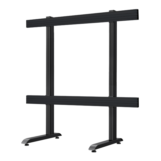
BT9370-SAM130
FLOOR STAND
FOR SAMSUNG'S ALL-IN-ONE IAC 130" DISPLAY
INSTALLATION GUIDE
• Designed and con gured speci cally for the Samsung
All-in-One IAC 130" Display
• Created from System X components
• Incorporates Samsung 130" All-in-One IAC Series
mounting brackets
• Adjustable levelling feet to accomodate uneven oor surfaces
• Integrated cable management for a neat
• Dimensions:
W.2755mm (108.5") x H.2500mm (98.4") x D.950mm (37.4")
SPECIFICATIONS
www.btechavmounts.com
TM
130"
330
cm
Advertisement
Table of Contents

Related Manuals for B-Tech BT9370-SAM130


Summary of Contents for B-Tech BT9370-SAM130
- Page 1 BT9370-SAM130 FLOOR STAND FOR SAMSUNG’S ALL-IN-ONE IAC 130" DISPLAY INSTALLATION GUIDE SPECIFICATIONS • Designed and con gured speci cally for the Samsung All-in-One IAC 130" Display • Created from System X components • Incorporates Samsung 130" All-in-One IAC Series mounting brackets •...
- Page 2 It is recommended that periodic inspections of the product and its xing points are made as frequently as possible (no more than 6 months apart) to ensure that safety is maintained. B-Tech AV Mounts recommends that a suitably quali ed person is used for the removal of this product.
- Page 4 BT9370-SAM130 PARTS LIST PLEASE KEEP THIS FOR FUTURE REFERENCE *SUPPLIED WITH SAMSUNG’S ALL-IN-ONE IAC SERIES DISPLAY...
- Page 5 ITEM PART NAME BASE LEVELING FOOT M8 x 90mm SCREW M8 WASHER 6AF HEX KEY 24mm SPANNER 180cm COLUMN PLASTIC SLOT INSERT CABLE COVER COLUMN END CAP 60cm COLUMN 60cm PLASTIC SLOT INSERT COLUMN JOINER 3AF HEX KEY RAIL-TO-COLUMN FIXING PLATE M8 SLIDING NUT M8 x 12mm SCREW 5AF HEX KEY...
-
Page 6: Installation Instructions
INSTALLATION INSTRUCTIONS COMBINE COLUMNS i. Insert and secure item 13 halfway into the non-threaded end of item 7. Note: The two joining bars with grub screws go in the front of the column and the 2 joining bars with hex bolts go in the back. IMPORTANT: Joining bars should be inserted into the non-threaded end of... - Page 7 COMBINE RAILS i. On one side of item 19, insert 4x item 22 half-way into each channel. On the back side of item 19, insert 1x item 22 into the top channel and 1x item 22 into the third channel (see g. 1). Loosely fasten the grub screws on each joining bar securing it to the mounting rail.
- Page 8 ATTACH JOINING PLATES TO COLUMNS i. On item 15, assemble 4x item 17 to item 16. ii. Lay the column on the oor and t item 15 to items 7 & 11 (see g 2. for placement of item 15). Repeat for both columns.
- Page 9 INSERT SLIDING NUTS INTO MOUNTING RAILS Lay the rail on the oor and at either end insert 4x item 16 into item 19. Two in the 2nd channel and two in the bottom channel (See g. 3 for positioning of item 16). Repeat for both rails.
- Page 10 ATTACH COLUMNS TO RAILS On the oor, place items 7 & 11 onto items 19 & 20. Fix item 15 to items 19 & 20 by fastening item 17 into item 16. Note: To ensure straight assembly of items 19 & 20 make sure the distance of items 15 to the end of items 19 &...
- Page 11 ASSEMBLE BASES TO COLUMNS Attach item 1 to item 7 using items 3 & 4. Once bases are xed to columns, return stand to upright position. THREADED Note: If necessary item 6 to level and adjust item...
- Page 12 ATTACH SAMSUNG WALL PLATES TO TOP MOUNTING RAIL i. On the top rail, insert 24x item 24 into the top channel of item 19 & 20 (See g.4 for positioning of item 24). ii. Using items 24, 25 & 26, x 4x items 23 (supplied with screen) to items 19 &...
- Page 13 iii. On the lower rail, insert 2x item 24 into the bottom channel of items 19 & 20. Note: Refer to g.6 for the locations of item 24. Insert item 24 into the bottom channel of the lower mounting rail. BOTTOM RAIL 298mm 11.75in 298mm 11.75in...
- Page 14 HOOK THE SAMSUNG FRAME ONTO STAND i. Following the installation instructions of the Display, hook the Samsung frame onto item 23. SAMSUNG LED FRAME...
- Page 15 ii. Fix the bottom of the frame to the lower rail (items 19 & 20) using items 24, 25 & 27 and the holder ring (supplied with the Samsung display*). *Please refer to the display’s assembly manual. FRONT LOWER RAIL HOLDER RING Supplied with LED screen LED FRAME...
- Page 16 ADD COVERS AND END CAPS i. After screen cables are connected and routed down the back of item 7, partially clip on the cable management item 9, this allows easy removal if more cables need adding. Once satis ed all cables are tted, clip the covers on fully. ii.
-
Page 17: Front View
1750mm 68.9in 1000mm 39.4in 475mm 18.7in 1134.2mm 44.7in 475mm 18.7in (Excluding End Cap) (Excluding End Cap) 384.2mm 15.1in THESE INSTRUCTIONS ARE INTENDED AS A GUIDE ONLY AND B-TECH ACCEPTS NO LIABILITY FOR THE ACCURACY OF THE INFORMATION CONTAINED IN THIS DOCUMENT. -
Page 18: Side View
Samsung 130” Display 96.4mm 3.8in 60.6mm 2.4in 39mm 1.5in Samsung 130 IAC 39mm 1.5in 484.4mm 19.1in THESE INSTRUCTIONS ARE INTENDED AS A GUIDE ONLY AND B-TECH ACCEPTS NO LIABILITY FOR THE ACCURACY OF THE INFORMATION CONTAINED IN THIS DOCUMENT. - Page 19 (Max LED Display Width) Samsung 130 IAC 1659.2mm 65.3in TOP VIEW 408.2mm 16.1in Samsung 130 IAC 484.4mm 19.1in THESE INSTRUCTIONS ARE INTENDED AS A GUIDE ONLY AND B-TECH ACCEPTS NO LIABILITY FOR THE ACCURACY OF THE INFORMATION CONTAINED IN THIS DOCUMENT.
- Page 20 ©2024 B-Tech International Design and Manufacturing Ltd. All rights reserved. B-Tech AV Mounts is a division of B-Tech International Design and Manufacturing Ltd. B-Tech AV Mounts and the B-Tech logo are registered trade marks. All other brands and product names are trademarks of their respective owners.
Need help?
Do you have a question about the BT9370-SAM130 and is the answer not in the manual?
Questions and answers