Advertisement
Quick Links
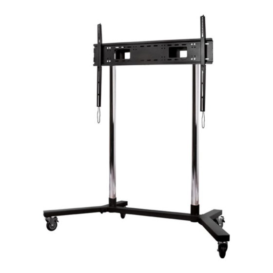
BT8506
X-LARGE FLAT SCREEN TROLLEY / STAND
INSTALLATION GUIDE & PARTS LIST
This Pack Contains 1 Trolley / Floor stand
PLEASE KEEP THIS FOR FUTURE REFERENCE
Installation Safety Notes.....................................................................................................................2
Parts List............................................................................................ . ................................................4
Safety Instructions...................................................................................................................................6
Product Assembly...............................................................................................................................7
Product Dimensions.................................................................................... . .....................................14
B-Tech Contact Details................................................................................ . ....................................16
INSTALLATION TOOLS REQUIRED
B-TECH AUDIO VIDEO MOUNTS
FEATURES
Designed for large flat screens up to 130kg
Universal interface kit fits screens with VESA and non-VESA
fixing patterns up to H.1100mm x V.730mm
Ideal for screens larger than 65" and heavy duty touch
screen displays
Simple 'hook on' installation with all mounting hardware included
Adjustment screws allows screen to be levelled once mounted
Non marking 4" locking/braked castors included - Also supplied
with optional screw-in levelling feet
1.5m Ø60mm poles supplied with 5 cable management holes
Trolley dimensions (including wheels):
H.1670mm x W.1660mm x D.800mm
CONTENTS
Crosshead
screwdriver
www.btechavmounts.com
130kg
(287Ibs)
Hex Keys
(Supplied)
Advertisement

Related Manuals for B-Tech BT8506


Summary of Contents for B-Tech BT8506
-
Page 1: Table Of Contents
H.1670mm x W.1660mm x D.800mm 130kg (287Ibs) CONTENTS Installation Safety Notes........................2 Parts List.............................4 Safety Instructions...........................6 Product Assembly..........................7 Product Dimensions..........................14 B-Tech Contact Details........................16 INSTALLATION TOOLS REQUIRED Hex Keys Crosshead (Supplied) screwdriver B-TECH AUDIO VIDEO MOUNTS www.btechavmounts.com... -
Page 2: Installation Safety Notes
INSTALLATION SAFETY INSTRUCTIONS CAUTION: This trolley / stand is intended for use only with the maximum weights indicated. Use with flat screen heavier than the maximum indicated may result in instability causing possible injury. ... - Page 3 CS Spole nost B-Tech International Ltd. doporu uje provést instalaci tohoto produktu prost ednictvím odborného instalátora AV i jinak zp sobilé osoby. Spole nost B-Tech International Ltd, její distributo i a prodejci nenesou odpov dnost za škody nebo zran ní zp sobená nevhodnou instalací. Tento výrobek je nutno umístit do vhodné konstrukce a pou vat jen po uvedenou maximální...
-
Page 4: Parts List
BT8506 PARTS LIST Suitable for loads up to 130kg... - Page 5 Flat Screen Interface Kit (For attaching mount to back of flat screen) PART NAME LEFT BASE LEG RIGHT BASE LEG BASE CENTRE MOUNTING PLATE WITH COLLARS INTERFACE ARM BACK COVER BRAKED CASTOR LEVELLING FOOT POLE END CAP 1.5M Ø60mm POLE M8 x 12mm SCREW M8 SPRING WASHER M6 x 200mm SCREW...
-
Page 6: Safety Instructions
WARNING CAN TIP OVER WHICH MAY LEAD TO SERIOUS INJURY. DO NOT ALLOW CHILDREN UNDER 16 TO MOVE TROLLEY. MOVE TROLLEY SLOWLY ALWAYS APPLY BRAKES WHEN NEVER LEAVE TROLLEY ON AN INCLINE. TROLLEY IS STATIONARY ALWAYS PARK ON LEVEL GROUND RELEASE BRAKES WHEN PUSHING TROLLEY. -
Page 7: Product Assembly
PRODUCT ASSEMBLY BASE A SSEMBLY Attach leg bases (parts 1 & 2) to the base centre (part 3) using M10 x 20mm screws and washers (parts 15 & 16) and allen key (part 19). THERE ARE TWO APPLICATIONS FOR THE BASE: MOBILE OR FIXED i) Select the braked castors (part 7) for a mobile application ii) Select the leveling feet (part 8) for a fixed application i) Screw the braked castors (part 7) - Page 8 Attach the poles (part 10) to the trolley base using the grub screws. BACK VIEW Grub screw The grub screws can also be used on the front side to align the poles if required. FRONT VIEW Grub ...
- Page 9 Fix mounting plate (part 4) at desired height on poles (part 10) by tightening pre-fitted screws on all collars. Fasten the M6 x 20mm screws tightly and ensure the gap between the collar halves on both sides are equal...
- Page 10 SCREEN MOUNTING INTSTRUCTIONS Attach interface arms (parts 5) to the back of the screen using the interface kit provided. Rear of screen Use the provided spacers (part L or M) for recessed flat screens. TOP OF SCREEN...
- Page 11 Hook the screen onto mounting plate (part 4). Use the pull string to ensure the interface arms (part 5) hook onto the mounting plate (part 4) securely. Pull string Once the bottom hook is in place, insert security screw (part 14) to lock screen.
- Page 12 LEVEL ADJUSTMENT (Optional) Insert M6 x 200mm screw (part 13) through the top of the interface arm (part 5) and level the flat screen by adjusting the depth of the screw.
- Page 13 Attach back cover (part 6) to the collars by using the M8 x 12mm screws and M8 spring washers (parts 11 & 12). Power socket extension Alternatively, the back cover (part 6) can be attached upside down to hold power socket extensions and leads.
-
Page 14: Product Dimensions
BT8506 PRODUCT DIMENSIONS Ø 60mm 810mm 1660mm 1070mm 990mm 820mm 1556mm 1660mm THESE INSTRUCTIONS ARE INTENDED AS A GUIDE ONLY AND B-‐TECH ACCEPTS NO LIABILITY FOR THE ACCURACY OF THE INFORMATION CONTAINED IN THIS DOCUMENT. - Page 15 BT8506 PRODUCT DIMENSIONS 1150mm MAX : 1100mm 10.50mm 31mm 35mm 1040mm 276mm 30mm 820mm THESE INSTRUCTIONS ARE INTENDED AS A GUIDE ONLY AND B-‐TECH ACCEPTS NO LIABILITY FOR THE ACCURACY OF THE INFORMATION CONTAINED IN THIS DOCUMENT.
-
Page 16: B-Tech Contact Details
B-Tech & Better By Design are registered trademarks of B-Tech International Limited. All other brands and product names are trademarks of their respective owners. Photographs are for illustrative purposes only. E&OE. AMA-BT8506-V1.1-PROBX-0115-44 MADE IN P.R.C.
Need help?
Do you have a question about the BT8506 and is the answer not in the manual?
Questions and answers