Table of Contents
Advertisement
Quick Links
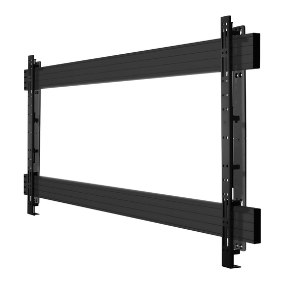
BT9920
XXL DISPLAY Wall Mount
INSTALLATION GUIDE
SPECIFICATIONS
• Designed to wall mount extra large signage displays up
to 120" such as LG's 110UM5J
• Suitable for standard or interactive screens over 72"
• Max load: 200kg (440lbs)
• Fits screens with VESA
to 1600 x 800mm
• Low profile design mounts screen 52mm (2") from wall
• Cable management
• Simple 'hook-on' installation with all mounting
hardware included
®
and non-VESA fixings up
www.btechavmounts.com
TM
Advertisement
Table of Contents

Related Manuals for B-Tech BT9920


Summary of Contents for B-Tech BT9920
- Page 1 BT9920 XXL DISPLAY Wall Mount INSTALLATION GUIDE SPECIFICATIONS • Designed to wall mount extra large signage displays up to 120” such as LG's 110UM5J • Suitable for standard or interactive screens over 72" • Max load: 200kg (440lbs) ® • Fits screens with VESA...
-
Page 2: Installation Safety Instructions
Please check carefully to make sure there are no missing or defective parts - defective parts must never be used. B-Tech AV Mounts, its distributors and dealers are not liable or responsible for damage or injury caused by improper installation, improper use or failure to observe these safety instructions. In such cases, all guarantees will expire. - Page 4 BT9920 PARTS LIST PLEASE KEEP THIS FOR FUTURE REFERENCE...
-
Page 5: Installation Tools Required
DESCRIPTION ITEM WALL PLATE M8 SLIDING INSERT M8 x 12mm CSK SCREW MOUNTING RAIL RAIL END CAP INTERFACE ARM CABLE MANAGEMENT CLIP M8 x 10mm HEX SCREW 5AF HEX KEY 5AF LONG HEX KEY SCREEN FIXING KIT M6 x 16mm CROSS SCREW M6 x 25mm CROSS SCREW M6 x 40mm CROSS SCREW M8 x 16mm CROSS SCREW... -
Page 6: Installation Instructions
INSTALLATION INSTRUCTIONS ATTACH MOUNTING RAILS TO WALL PLATES i. Insert 4x item 2 in both ends of item 4. 2 in the top channel and 2 in the bottom channel and set approx.1500mm apart. Repeat for both rails. 1500mm (59") 108mm Middle of Wall Plates (item 1) (4.25") - Page 7 FIX MOUNT TO WALL i. Pre-drill holes for the wall fixings and insert 16x item A2*, assemble 4x item A1 into the top holes and leave approx. 10mm gap to hook on item 1. *Not required for wooden stud walls. ii.
- Page 8 FIX CABLE MANAGEMENT CLIPS TO RAILS i. In suitable postions along the bottom of the rail, insert item 2 into item 4. ii Fix item 7 to item 4 using items 2 & 8. ATTACH INTERFACE ARMS TO SCREEN Fix item 6 to the rear of the screen using the interface kit provided (items A - N). Note: Ensure interface arms are positioned the correct way round and the same holes are used on both arms.
- Page 9 HOOK SCREEN ONTO RAILS WALL Using item 6, hook the screen onto both mounting rails (item 4). Note: This procedure may require two people. SCREEN LEVEL SCREEN & SECURE MOUNT i. Optional: Ensure the screen is level using the height adjustment screws on top of item 6. ii.
- Page 10 INSTALLATIONS FLOOR-TO-CEILING CEILING BT7052 (X8) BT9920 (X1) BT7850-200 (X2) BT7807 (X2) Additional M8 x 12mm CSK screws & M8 sliding nuts (BT6183) required for installation FLOOR-TO-WALL WALL BT7831 (X1) BT7052 (X8) BT9920 (X1) BT7850-200 (X2) BT7807 (X1)
-
Page 11: Front View
24mm 24mm SIDE VIEW 8.4mm 8.4mm 51.8mm TOP VIEW CABLE MANAGEMENT CLIP 1755mm 1750mm 44mm 51mm 30mm THESE INSTRUCTIONS ARE INTENDED AS A GUIDE ONLY AND B-TECH ACCEPTS NO LIABILITY FOR THE ACCURACY OF THE INFORMATION CONTAINED IN THIS DOCUMENT. - Page 12 ©2022 B-Tech International Design and Manufacturing Ltd. All rights reserved. B-Tech AV Mounts is a division of B-Tech International Design and Manufacturing Ltd. B-Tech AV Mounts and the B-Tech logo are registered trade marks. All other brands and product names are trademarks of their respective owners.
Need help?
Do you have a question about the BT9920 and is the answer not in the manual?
Questions and answers