
Related Manuals for National Instruments NI 447 Series


Summary of Contents for National Instruments NI 447 Series
- Page 1 NI 447X User Manual Dynamic Signal Acquisition Devices for PCI and PXI/CompactPCI NI 447X User Manual April 2003 Edition Part Number 322940C-01...
- Page 2 Switzerland 41 56 200 51 51, Taiwan 886 2 2528 7227, United Kingdom 44 0 1635 523545 For further support information, refer to the Technical Support and Professional Services appendix. To comment on the documentation, send email to techpubs@ni.com. © 2001–2003 National Instruments Corporation. All rights reserved.
- Page 3 The reader should consult National Instruments if errors are suspected. In no event shall National Instruments be liable for any damages arising out of or related to this document or the information contained in it.
- Page 4 These classes are known as Class A (for use in industrial-commercial locations only) or Class B (for use in residential or commercial locations). All National Instruments (NI) products are FCC Class A products. Depending on where it is operated, this Class A product could be subject to restrictions in the FCC rules. (In Canada, the Department of Communications (DOC), of Industry Canada, regulates wireless interference in much the same way.) Digital...
- Page 5 Conventions The following conventions are used in this manual: <> Angle brackets that contain numbers separated by an ellipsis represent a range of values associated with a bit or signal name—for example, DIO<3..0>. » The » symbol leads you through nested menu items and dialog box options to a final action.
- Page 6 NI PCI/PXI-4472 NI PCI/PXI-4472 refers to the NI PCI-4472, NI PXI-4472, and NI PXI-4472B unless otherwise noted. NI PXI-4472 NI PXI-4472 refers to the NI PXI-4472 and NI PXI-4472B unless otherwise noted. A high-performance expansion bus architecture originally developed by Intel to replace ISA and EISA, it is now accepted as a standard for PCs and workstations, and offers a theoretical maximum transfer rate of 132 Mbytes/s.
-
Page 7: Table Of Contents
About the NI 447X ......................1-1 What You Need to Get Started ..................1-2 Related Documentation....................1-2 Unpacking ........................1-3 Software Programming Choices ..................1-3 NI-DAQ......................1-3 National Instruments ADE Software...............1-4 Using PXI with CompactPCI..................1-5 Safety Information ......................1-6 Chapter 2 Using the NI 447X Installing the Software ....................2-1 Installing the Hardware....................2-1... - Page 8 Contents The ADC ......................3-9 Noise ....................... 3-10 Triggering ........................3-11 Synchronizing Multiple Devices ................... 3-14 Delta-Sigma ADCs and the Oversample Clock ..........3-14 The NI 447X SYNC Pulse ................3-15 The Acquisition Start Trigger ................. 3-17 Chapter 4 Calibration Loading Calibration Constants ..................
-
Page 9: Getting Started With The Ni 447X
About the NI 447X The NI 447X devices are high-performance, high-accuracy analog input devices that are part of the National Instruments Dynamic Signal Acquisition/Analysis (DSA) product family. These devices are specifically designed for demanding dynamic signal acquisition applications. -
Page 10: What You Need To Get Started
Chapter 1 Getting Started with the NI 447X What You Need to Get Started To set up and use the NI 447X devices, you need the following items: ❑ One of the following devices: – NI PCI-4472 – NI PCI-4474 –... -
Page 11: Unpacking
Store the NI 447X device in the antistatic envelope when not in use. Software Programming Choices When programming National Instruments data acquisition (DAQ) hardware, you can use an NI application development environment (ADE) or other ADEs. In either case, you use NI-DAQ. -
Page 12: National Instruments Ade Software
Measurement Studio, which includes tools for Visual C++ and tools for Visual Basic, is a development suite that allows you to design test and measurement applications. For Visual Basic developers, Measurement Studio features a set of ActiveX controls for using National Instruments NI 447X User Manual ni.com... -
Page 13: Using Pxi With Compactpci
NI PXI-4472 is compatible with any CompactPCI chassis with a sub-bus that does not drive these lines. Even if the sub-bus is capable of driving these lines, the NI PXI-4472 is still compatible as long as those pins on the © National Instruments Corporation NI 447X User Manual... -
Page 14: Safety Information
Chapter 1 Getting Started with the NI 447X sub-bus are disabled by default and not ever enabled. Damage may result if these lines are driven by the sub-bus. Table 1-1. J2 Connector Pins Used by the NI PXI-4472 NI PXI-4472 Signal PXI Pin Name PXI J2 Pin Number Master Clock Distribution... - Page 15 Working voltage is the highest rms value of an AC or DC voltage that can occur across any particular insulation. MAINS is defined as a hazardous live electrical supply system that powers equipment. Suitably rated measuring circuits may be connected to the MAINS for measuring purposes. © National Instruments Corporation NI 447X User Manual...
- Page 16 Chapter 1 Getting Started with the NI 447X • Installation Category III is for measurements performed in the building installation at the distribution level. This category refers to measurements on hard-wired equipment such as equipment in fixed installations, distribution boards, and circuit breakers. Other examples are wiring, including cables, bus-bars, junction boxes, switches, socket-outlets in the fixed installation, and stationary motors with permanent connections to fixed installations.
-
Page 17: Using The Ni 447X
Note It is important to install NI-DAQ before installing the NI 447X to ensure that the device is properly detected. © National Instruments Corporation NI 447X User Manual... - Page 18 Chapter 2 Using the NI 447X ♦ NI PCI-4472 and NI PCI-4474 Power off and unplug the computer. Remove the cover. Make sure there are no lighted LEDs on the motherboard. If any are lit, wait until they go out before continuing the installation. Remove the expansion slot cover on the back panel of the computer.
-
Page 19: Testing The Device
DAQ Quick Start Guide included with the device. You can modify data acquisition-related settings, such as input coupling, through NI application-level software, such as LabVIEW or Measurement Studio, or with NI-DAQ. Refer to device configuration instructions in the © National Instruments Corporation NI 447X User Manual... -
Page 20: Connecting Signals
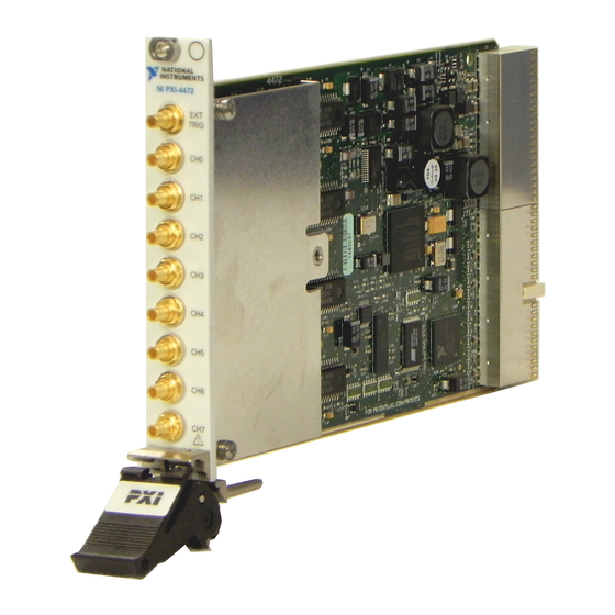
Chapter 2 Using the NI 447X NI-DAQ documents and in the NI-DAQ Function Reference Help (Start»Programs»National Instruments»DAQ»NI-DAQ Help) for more information. Connecting Signals The front panels of the NI PCI/PXI-4472 devices are shown in Figure 2-1, and the NI PCI-4474 front panel is shown in Figure 2-2. There are eight... - Page 21 Chapter 2 Using the NI 447X NI PXI-4472 NI PXI-4472B TRIG TRIG TRIG NI PXI-4472 NI PXI-4472B NI PCI-4472 Figure 2-1. NI PCI/PXI-4472 Front Panels © National Instruments Corporation NI 447X User Manual...
- Page 22 Chapter 2 Using the NI 447X TRIG NI PCI-4474 Figure 2-2. NI PCI-4474 Front Panel Before configuring the AI channels and making signal connections, you must determine the following: • Whether the input signal source is floating or grounded • Whether the accelerometer or microphone you are using requires IEPE current stimulation NI 447X User Manual...
-
Page 23: Signal Sources
Connecting a signal that varies more than ±2.5 V from the ground reference of the NI 447X to the ground (shield) of any AI channel can result in inaccurate measurements or damage to the device. NI is not responsible for damage caused by such connections. © National Instruments Corporation NI 447X User Manual... -
Page 24: Floating Signal Sources
Chapter 2 Using the NI 447X Floating Signal Sources A floating signal source does not connect in any way to the building ground system but instead has an isolated ground-reference point. Some examples of floating signal sources are outputs of transformers, thermocouples, battery-powered devices, optical isolator outputs, and isolation amplifiers. -
Page 25: Generating Onboard Current Excitation With Iepe Circuitry
NI 447X (except the NI PXI-4472B). The −0.1 dB cutoff frequency is approximately 22.2 Hz. ♦ NI PXI-4472B The −3 dB cutoff frequency is approximately 0.5 Hz for the NI PXI-4472B. The −0.1 dB cutoff frequency is approximately 3.2 Hz. © National Instruments Corporation NI 447X User Manual... -
Page 26: Input Polarity And Input Range
Chapter 2 Using the NI 447X Input Polarity and Input Range Caution Connections that exceed the rated input voltages can damage the computer and the connected equipment. Overvoltage protection is ±42.4 V on the positive signal line. The shield does not have overvoltage protection. Do not make a non-ground connection to the shield. -
Page 27: Field Wiring Considerations
Do not run signal lines through conduits that also contain power lines. • Protect signal lines from magnetic fields caused by electric motors, welding equipment, breakers, or transformers by running them through dedicated metal conduits. © National Instruments Corporation 2-11 NI 447X User Manual... -
Page 28: Selecting The Sample Clock Frequency
Chapter 2 Using the NI 447X Selecting the Sample Clock Frequency The eight AI channels of the NI PCI/PXI-4472 and the four AI channels of the NI PCI-4474 are simultaneously sampled at any software-programmable rate from 102.4 kS/s down to 1.0 kS/s in 190.7 µS/s increments for f >... - Page 29 For using NI-DAQ with other ADEs, refer to Synchronizing Multiple PCI-DSA Devices: Select_Signal in the NI-DAQ Function Reference Help (for NI-DAQ 6.9.x) or the Traditional NI-DAQ C Reference Help (for NI-DAQ 7.x). Select Start»Programs»National Instruments»NI-DAQ and the document title for the version of NI-DAQ you are using. ♦...
-
Page 30: Device Configuration Issues
Chapter 2 Using the NI 447X Device Configuration Issues When testing your NI 447X, it is important to remember that it is equipped with high performance antialiasing filters. Because of these filters, you cannot acquire a signal whose fundamental frequency exceeds one half the sampling rate. -
Page 31: Device Overview And Theory Of Operation
Figure 3-2. Mini MITE AI FIFO PCI Controller DMA Control Synchronization Clock Control General Control To ADCs DDS Clock Generator Figure 3-1. Digital Function Block Diagram © National Instruments Corporation NI 447X User Manual... -
Page 32: I/O Connectors
Chapter 3 Device Overview and Theory of Operation EXT Digital Trigger FIFO INPUT/CAL AC/DC Serial/IO Hardware Linear LP Filter ADC0 Coupling Parallel Correction FIFO INPUT/CAL AC/DC Serial/IO Hardware Linear LP Filter ADC1 Coupling Parallel Correction CH<0.. n– 1> CH<0.. n– 1> CH<0.. -
Page 33: Analog Input Signal Connections
> 51.2 kS/s or 95.37 µS/s increments for ≤ 51.2 kS/s. This flexibility in sample rates makes the device well-suited for a wide variety of applications, including audio, acoustics, and vibration analysis. © National Instruments Corporation NI 447X User Manual... -
Page 34: Calibration
Chapter 3 Device Overview and Theory of Operation The unbalanced differential analog inputs have software-selectable AC/DC coupling. Calibration The NI 447X analog inputs have calibration adjustments. Onboard calibration circuits remove the offset and gain errors for each channel. For complete calibration instructions, refer to Chapter 4, Calibration. Antialias Filtering Any sampling system (such as an ADC) is limited in the bandwidth of the signals it can represent. - Page 35 Because the filter employs an FIR (Finite Impulse Response) architecture, its phase response is perfectly linear. Figures 3-4 and 3-5 show the frequency response of the NI 447X input circuitry. © National Instruments Corporation NI 447X User Manual...
- Page 36 Chapter 3 Device Overview and Theory of Operation 0.00 –20.00 –40.00 –60.00 –80.00 –100.00 –120.00 0.00 0.20 0.40 0.60 0.80 1.00 Frequency/Sample Rate ( f Figure 3-4. Input Frequency Response 0.00 –1.00 –2.00 –3.00 –4.00 –5.00 –6.00 0.43 0.44 0.45 0.46 0.47 0.48...
- Page 37 This graph accounts for the response of both the digital and analog filters. The rejection ratio is better than 110 dB for all aliases outside plus or minus one Nyquist bandwidth of multiples of 64 or 128 times f © National Instruments Corporation NI 447X User Manual...
- Page 38 Chapter 3 Device Overview and Theory of Operation Alias Rejection (dB) 0.00 –10.00 –20.00 –30.00 –40.00 –50.00 –60.00 –70.00 –80.00 –90.00 –100.00 Sample Rate (kS/s) 10.0 100.0 200.0 Oversample 128 kHz 1.28 MHz 6.4 MHz Frequency 128 f 64 f Figure 3-6.
-
Page 39: The Adc
25.6 kHz. This noise is not © National Instruments Corporation NI 447X User Manual... -
Page 40: Noise
Chapter 3 Device Overview and Theory of Operation correlated with the input signal and is almost completely rejected by the digital filter. The resulting output of the filter is a band-limited signal with a dynamic range of more than 100 dB. One of the advantages of a delta-sigma ADC is that it uses a 1-bit DAC as an internal reference. -
Page 41: Triggering
Five analog level triggering modes are available, as shown in Figures 3-8 through 3-12. You can set lowValue and highValue independently in the software. © National Instruments Corporation 3-11 NI 447X User Manual... - Page 42 Chapter 3 Device Overview and Theory of Operation In below-low-level triggering mode, shown in Figure 3-8, the trigger is generated when the signal value is less than lowValue. highValue is unused. lowValue Trigger Figure 3-8. Below-Low-Level Triggering Mode In above-high-level triggering mode, shown in Figure 3-9, the trigger is generated when the signal value is greater than highValue.
- Page 43 NI 447X except RTSI 5/TRIG 5, which is reserved for internal use when synchronizing multiple NI 447X devices. Note A PXI chassis with multiple PXI buses might not have RTSI connections across the bus boundaries. © National Instruments Corporation 3-13 NI 447X User Manual...
-
Page 44: Synchronizing Multiple Devices
Chapter 3 Device Overview and Theory of Operation Synchronizing Multiple Devices This section provides low-level background information about the electrical signals needed to tightly synchronize NI 447X modules. This section describes three signals: the oversample clock, the SYNC pulse, and the acquisition start trigger. Delta-Sigma ADCs and the Oversample Clock The 24-bit ADCs employed on the NI 447X belong to a class of components called delta-sigma (or ∆Σ) ADCs. -
Page 45: The Ni 447X Sync Pulse
ADCs. For this reason, the NI 447X and other National Instruments DSA products do not support external clocking from arbitrary signal sources. The NI 447X SYNC Pulse... - Page 46 Chapter 3 Device Overview and Theory of Operation at exactly the same time. Figure 3-13 illustrates the oversample pulse trains on two NI 447X devices sampling at 102.4 kS/s. In this example, there is a delay between acquisition samples of five oversample intervals, or about 350 ns.
-
Page 47: The Acquisition Start Trigger
ADCs on every NI 447X in the system run in lock-step. At this point, the only remaining task is to synchronize the beginning of the data acquisition on each NI 447X. You can choose RTSI <0..4>/TRIG <0..4> for the start trigger. © National Instruments Corporation 3-17 NI 447X User Manual... -
Page 48: Calibration
Initiate self-calibration by calling the DSA Calibrate VI or the function. This self-calibration Calibrate_DSA process, which generally takes less than a minute, is the preferred method of assuring accuracy in your application. Initiate self-calibration to © National Instruments Corporation NI 447X User Manual... -
Page 49: External Calibration
Chapter 4 Calibration minimize the effects of any offset and gain drifts, particularly those due to temperature variations. The NI 447X has an onboard calibration reference to ensure the accuracy of self-calibration. Its specifications are listed in Appendix A, Specifications. The reference voltage is measured at the factory or during an external calibration operation and stored in the EEPROM for subsequent self-calibrations. -
Page 50: Traceable Recalibration
NI 447X at your location (on-site). You also can send the NI 447X to a third party for recalibration. Please contact NI for approved third-party calibration service providers. Calibration documentation and function libraries are available online at ni.com/calibration © National Instruments Corporation NI 447X User Manual... -
Page 51: Appendix A Specifications
> 51.2 kS/s or 95.37 µS/s for f ≤ 51.2 kS/s increments for f Frequency accuracy........ ±25 ppm Input signal range........±10 V peak FIFO buffer size ........1,024 samples Data transfers ......... DMA © National Instruments Corporation NI 447X User Manual... - Page 52 Appendix A Specifications Transfer Characteristics Offset (residual DC) .......±3 mV, max Gain (amplitude accuracy)......±0.1 dB, max, ƒ = 1 kHz Amplifier Characteristics Input impedance (ground referenced) Positive input ........1 MΩ in parallel with 60 pF Negative input (shield) ....50 Ω in parallel with 0.02 µF Flatness (relative to 1 kHz).....±0.1 dB, DC to 0.4535 f , max, DC-coupled...
- Page 53 16,384 points, 51.2 kS/s, 10 averages 1.0 m 100.0 µ 10.0 µ 1.0 µ 100.0 n 10.0 n 10.0 100.0 1.0 k 10.0 k 25.6 k Frequency (Hz) Figure A-2. Input Noise Spectral Density at 128-Times Oversampling © National Instruments Corporation NI 447X User Manual...
- Page 54 Appendix A Specifications Spectral Noise Density, referred to input 16,384 points, 102.4 kS/s, 10 averages 1.0 m 100.0 µ 10.0 µ 1.0 µ 100.0 n 10.0 n 12.5 100.0 1.0 k 10.0 k 51.2 k Frequency (Hz) Figure A-3. Input Noise Spectral Density at 64-Times Oversampling Dynamic Characteristics Alias-free bandwidth (passband) ....DC (0 Hz) to 0.4535 f Stop band ..........0.5465 f...
- Page 55 16,384 points, 102.4 kS/s –20.0 –40.0 –60.0 –80.0 –100.0 –120.0 –140.0 –160.0 5000 10000 15000 20000 25000 30000 35000 40000 45000 51194 Frequency (Hz) Figure A-5. Spurious-Free Dynamic Range at 102.4 kS/s © National Instruments Corporation NI 447X User Manual...
- Page 56 Appendix A Specifications 0 dBFS input........<−90 dB –20 dBFS input........<–100 dB –60 dBFS input........<–60 dB IMD ............<–100 dB (CCIF 14 kHz + 15 kHz) Crosstalk (channel separation), f = 0 to 51.2 kHz Between channels 0 and 1, 2 and 3, 4 and 5, or 6 and 7 Shorted input ......<–90 dB 1 kΩ...
- Page 57 NI PXI-4472 ........400 mA, max +5 VDC NI PCI-4472........2,600 mA, max NI PCI-4474........2,000 mA, max NI PXI-4472 ........2,200 mA, max +12 VDC ..........120 mA, max –12 VDC ..........120 mA, max © National Instruments Corporation NI 447X User Manual...
- Page 58 Appendix A Specifications Physical Dimensions (not including connectors) NI PCI-4472/4474 ......17.5 by 10.7 cm (6.9 by 4.2 in.) NI PXI-4472/4472B ......16.0 by 9.9 cm (6.3 by 3.9 in.) (1 3U CompactPCI slot) Analog I/O connectors......SMB male Digital trigger connector......SMB male Calibration Internal............On software command;...
- Page 59 Select the appropriate product family, followed by your product, and a link to the DoC appears in Adobe Acrobat format. Click the Acrobat icon to download or read the DoC. © National Instruments Corporation NI 447X User Manual...
- Page 60 Technical Support and Professional Services Visit the following sections of the National Instruments Web site at for technical support and professional services: ni.com • Support—Online technical support resources include the following: – Self-Help Resources—For immediate answers and solutions, visit our extensive library of technical support resources available in English, Japanese, and Spanish at .
- Page 61 Appendix B Technical Support and Professional Services • Calibration Certificate—If your product supports calibration, you can obtain the calibration certificate for your product at ni.com/calibration If you searched and could not find the answers you need, contact ni.com your local office or NI corporate headquarters. Phone numbers for our worldwide offices are listed at the front of this manual.
- Page 62 Numbers/Symbols ° degree Ω percent positive of, or plus – negative of, or minus amperes analog-to-digital alternating current AC coupled allowing the transmission of AC signals while blocking DC signals © National Instruments Corporation NI 447X User Manual...
- Page 63 Glossary analog-to-digital converter—an electronic device, often an integrated circuit, that converts an analog voltage to a digital number ADC resolution the size of the discrete steps in the ADCs input-to-output transfer function; therefore, the smallest voltage difference an ADC can discriminate with a single measurement application development environment—an application designed to make it easier for you to develop software.
- Page 64 DAQ device to supply current for analog or digital output signals © National Instruments Corporation NI 447X User Manual...
- Page 65 Glossary data acquisition—(1) collecting and measuring electrical signals from sensors, transducers, and test probes or fixtures and inputting them to a computer for processing; (2) collecting and measuring the same kinds of electrical signals with A/D and/or DIO devices plugged into a computer, and possibly generating control signals with D/A and/or DIO devices in the same computer decibel—the unit for expressing a logarithmic measure of the ratio of...
- Page 66 A/D conversion © National Instruments Corporation NI 447X User Manual...
- Page 67 Glossary FIFO first-in first-out memory buffer—the first data stored is the first data sent to the acceptor. FIFOs are often used on DAQ devices to temporarily store incoming or outgoing data until that data can be retrieved or output. For example, an analog input FIFO stores the results of A/D conversions until the data can be retrieved into system memory, a process that requires the servicing of interrupts and often the programming of the DMA controller.
- Page 68 LSB of the worst-case deviation from the ideal A/D or D/A transfer characteristic of the analog I/O circuitry input impedance the measured resistance and capacitance between the input terminals of a circuit and ground © National Instruments Corporation NI 447X User Manual...
- Page 69 Glossary interrupt a computer signal indicating that the CPU should suspend its current task to service a designated activity interrupt request kilo—the standard metric prefix for 1,000, or 10 , used with units of measure such as volts, hertz, and meters 1,000 samples LabVIEW laboratory virtual instrument engineering workbench...
- Page 70 Nyquist frequency © National Instruments Corporation NI 447X User Manual...
- Page 71 Glossary passband the range of frequencies which a device can properly propagate or measure Peripheral Component Interconnect—a high-performance expansion bus architecture originally developed by Intel to replace ISA and EISA. It is achieving widespread acceptance as a standard for PCs and work-stations; it offers a theoretical maximum transfer rate of 132 Mbytes/s.
- Page 72 DSA device that has an extremely stable onboard reference and calibrates its own A/D and D/A circuits without manual adjustments by the user © National Instruments Corporation G-11 NI 447X User Manual...
- Page 73 Glossary sensor a device that responds to a physical stimulus (heat, light, sound, pressure, motion, flow, and so on), and produces a corresponding electrical signal Shannon Sampling Nyquist Sampling Theorem. Theorem signal conditioning the manipulation of signals to prepare them for digitizing a type of coaxial connector signal-to-noise ratio—the ratio of the overall rms signal level to the rms noise level, expressed in decibels...
- Page 74 See also differential input. undersampling sampling at a rate lower than the Nyquist frequency—can cause aliasing volts collector common voltage—power supply voltage volts direct current © National Instruments Corporation G-13 NI 447X User Manual...
- Page 75 Glossary virtual instrument—(1) a combination of hardware and/or software elements, typically used with a PC, that has the functionality of a classic stand-alone instrument; (2) a LabVIEW software module (VI), which consists of a front panel user interface and a block diagram program volts in reference voltage waveform...
- Page 76 2-12 CompactPCI transfer characteristics, A-2 installing NI PXI-4472 (note), 2-2 antialias filtering using with PXI, 1-5 alias rejection at oversample rate configuration (figure), 3-8 device configuration issues, 2-14 testing, 2-3 © National Instruments Corporation NI 447X User Manual...
- Page 77 Index connecting signals. See signal connections contacting National Instruments, B-2 field wiring considerations, 2-11 conventions used in the manual, v filtering. See antialias filtering current excitation, generating with IEPE floating signal sources circuitry, 2-9 description, 2-8 customer input configurations (figure), 2-7...
- Page 78 IEPE circuitry, 2-9 technical support, B-1 online technical support, B-1 worldwide offices, B-2 operation of NI 447X. See theory of operation National Instruments application software, 1-4 overranged waveform, 3-8 NI 4472 oversample clock front panel (figure), 2-5 delta-sigma ADCs, 3-14...
- Page 79 RTSI 5/TRIG 5 signal for synchronization input configurations (figure), 2-7 (caution), 2-12 software drivers, B-1 software installation, 2-1 software programming choices National Instruments application safety information, 1-6 software, 1-3 safety specifications, A-9 NI-DAQ driver software, 1-3 sample clock, 3-14 specifications...
- Page 80 B-2 above-high-level triggering mode (figure), 3-12 below-low-level triggering mode (figure), 3-12 high-hysteresis triggering mode (figure), 3-13 inside-region triggering mode (figure), 3-12 low-hysteresis triggering mode (figure), 3-13 traceable recalibration, 4-3 © National Instruments Corporation NI 447X User Manual...
Need help?
Do you have a question about the NI 447 Series and is the answer not in the manual?
Questions and answers