Dean D20 Series Installation & Operation Manual
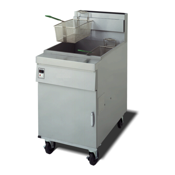
Decathlon series gas fryers (non-ce)
Hide thumbs
Also See for D20 Series:
- Installation and operation manual (44 pages) ,
- Installation & operation manual (43 pages) ,
- Service & parts manual (76 pages)

Related Manuals for Dean D20 Series


Summary of Contents for Dean D20 Series
- Page 1 D20, D50, D60 & D80 Series Dean, a member of the Commercial Food Equipment Service Association, recommends using CFESA Certified Technicians. 24-Hour Service Hotline 1-800-551-8633 AUGUST 2003 *8195698*...
- Page 3 If a flexible gas line is used, an additional restraining cable must be connected at all The front ledge of the fryer is not a step. Do not stand on the fryer. Serious injury can result Do not store or use gasoline or other flammable vapors and liquids in the vicinity of this or any Instructions to be followed in the event the operator smells gas or otherwise detects a gas leak must be posted in a prominent location.
-
Page 4: Table Of Contents
Rating Plate Pre-Installation Air Supply and Ventilation Equipment Installed at High Altitudes INSTALLATION Installing the Fryer Leveling the Fryer (Fryers equipped with legs only) Installing Casters and Legs Gas Connections Adjustments/Adaptation to Different Gases Electrical Connections FRYER OPERATIONS Initial Start-up... - Page 5 Decathlon Series Gas Fryers Installation & Operation Manual TABLE OF CONTENTS (CONT.) CONTROLLER OPERATING INSTRUCTIONS Operating Instructions: Electronic Thermostat Controller Electronic Thermostat Controller/Computer with Back-Up Thermostat PREVENTATIVE MAINTENANCE General TROUBLESHOOTING General Pilot Burner Malfunction Main Burner Malfunctions Electronic Thermostat Calibration Page #...
- Page 6 FINDING YOUR WAY AROUND THE DEAN DECATHLON Basket Hanger Flue Cap Frypot Top Cap Electronic Operating Thermostat Burners 1.5” Round Drains Drain Tubes Drain Valve Handle (Red) Filter Unit Oil Return Handle (Yellow) Drain Flush Handle (Blue) Drain Tubes 3” Round Drains (SCFD models)
-
Page 7: Introduction
DECATHLON SERIES GAS FRYERS (NON-CE) CHAPTER 1: INTRODUCTION 1.1 After Purchase In order to improve service, have the following chart filled in by the Dean Authorized Service Technician who installed this equipment. Authorized Service Technician/FASC Address Telephone/Fax Model Number Serial Number Gas Type 1.2 Ordering Parts Customers may order parts directly from their local factory authorized service center. -
Page 8: Safety Information
DECATHLON SERIES GAS FRYERS (NON-CE) CHAPTER 1: INTRODUCTION 1.4 Computer Information (cont.) The user is cautioned that any changes or modifications not expressly approved by the party responsible for compliance could void the user's authority to operate the equipment. If necessary, the user should consult the dealer or an experienced radio and television technician for additional suggestions. -
Page 9: Service Personnel
Dean equipment. A list of Dean Factory Authorized Service Centers (FASCs) was included with the fryer when shipped from the factory. Failure to use qualified service personnel will void the Dean warranty on your equipment. - Page 10 THIS PAGE INTENTIONALLY LEFT BLANK.
-
Page 11: Important Information
Carefully roll the unit down the ramps from the front (cooking side). E. Remove all plastic skin from sides, front, and doors of the fryer(s). Failure to do this prior to initial fryer operation will make it very difficult to remove later. - Page 12 DANGER Building codes prohibit a fryer with its open tank of hot oil/shortening from being installed beside an open flame of any type, including those of broilers and ranges.
-
Page 13: Rating Plate
This is attached to the inside front door panel. Information provided includes the model and serial number of the fryer, BTU/hr input of the burners, outlet gas pressure in inches W.C. and whether the unit has natural or propane gas orifices. -
Page 14: Air Supply And Ventilation
This appliance must be installed with sufficient ventilation to prevent the occurrence of unacceptable concentrations of substances harmful to the health of personnel in Keep the area around the fryer clear to prevent obstruction of combustion and ventilation airflow as well as for service and maintenance. -
Page 15: Equipment Installed At High Altitudes
CHAPTER 2: IMPORTANT INFORMATION 2.6 Air Supply and Ventilation (cont.) D. Do not place the fryer’s flue outlet directly into the plenum of the hood, as it will affect the gas combustion of the fryer. E. Never use the interior of the fryer cabinet for storage or store items on shelving over or behind the fryer. - Page 16 THIS PAGE INTENTIONALLY LEFT BLANK.
-
Page 17: Installation
A. Initial Installation: If the fryer is installed with legs, do not push the fryer to adjust its position. Use a pallet or lift jack to lift the fryer slightly, then place the fryer where it is to be installed. -
Page 18: Installing Casters And Legs
3.3 Installing Casters and Legs A. Install casters and/or legs near where the fryer is to be used, as neither is secure for long transit. Decathlon Series gas fryers cannot be curb mounted and must be equipped with either legs or casters provided. -
Page 19: Gas Connections
FASC should be contacted immediately to rectify the problem. A. The gas supply (service) line must be the same size or greater than the fryer inlet line. This fryer is equipped with a 3/4" (22 mm) male inlet. The gas supply line must be sized to accommodate all the gas-fired equipment that may be connected to that gas supply. - Page 20 D. Regulating Gas Pressure: The fryer and shut-off valve must be disconnected from the gas supply during any pressure testing of the system.
- Page 21 G. Only qualified service personnel should make adjustments to the regulators. H. Orifices: The fryer can be configured to operate on any available gas. The correct safety control valve, appropriate gas orifices, and pilot burner are installed at the factory. While the valve can be adjusted in the field, only qualified service personnel should make any adjustments with the proper test equipment.
-
Page 22: Adjustments/Adaptation To Different Gases
Gas pressure at the regulator (mbar)* * Gas pressure may vary per fryer model and altitude. Check the rating plate for specific gas pressures. NOTE: Outlet gas pressure must be adjusted strictly within the above requirements 5 to 10 minutes after the appliance is operating. - Page 23 Conversion of this appliance from one type of gas to another should only be performed by qualified, licensed, and authorized installation or service personnel, as defined in Section 1.6 of this manual. Contact factory with the following information when performing conversions: Fryer Serial Number Fryer Model Number Gas Type Operating Altitude Conversions can only be executed by qualified, factory-authorized personnel.
-
Page 24: Electrical Connections
DO NOT CUT, REMOVE, OR OTHERWISE BYPASS THE GROUNDING The rating plate and wiring diagram are located inside the front door. The fryer is equipped with a 120VAC single-phase 60-hertz system (Domestic), or 230VAC single-phase 50-hertz system (International/CE). -
Page 25: Fryer Operations
Typical high-limit/sensor probe locations and mounting hardware. Do not bang fry baskets or other utensils on the fryer’s joiner strip. The strip is present to seal the joint between the frypot. Banging fry baskets on the strip to dislodge shortening will distort the strip, adversely affecting its fit. - Page 26 The inlet pipe at the lower rear of the fryer brings incoming gas to the pilot safety control valve, then to the pilot and main burners. The pilot is located high in the cabinet center, at the base of the frypot.
-
Page 27: Boil-Out Procedure
Never leave the fryer unattended during the boil-out process. If the boil-out solution boils over, turn the fryer off immediately and let the solution cool for a few minutes before resuming the process. To lessen the chance of boil over, turn the fryer’s gas valve knob to the PILOT position occasionally. - Page 28 C. Filtration/Boil-Mode equipped fryers: Turn fryer power switch to "ON". Press the fryer- reset switch (if applicable). Turn the boil-out switch "ON". If the pilot and main burner go out, the fryer(s) MUST be left completely shut down at D. The main burner will ignite.
-
Page 29: Final Preparation
4.3.1 Filling Fryer with Shortening A. When using a liquid shortening, fill the fryer to the bottom OIL LEVEL line scribed into the back of the frypot. B. When using a solid shortening, first melt it in a suitable container, or cut it into small pieces and pack it below the heat tubes, between the tubes and on top of the tubes, leaving no air spaces around the tubes. - Page 30 DECATHLON SERIES GAS FRYERS (NON-CE) CHAPTER 4: FRYER OPERATIONS 4.3.1 Filling Fryer with Shortening (cont.) D. Operating Thermostat: Turn the burners "ON" for about 10 seconds, "OFF" for a minute, etc., until the shortening is melted. If you see smoke coming from the shortening while melting this way, shorten the "ON"...
-
Page 31: Controller Operating Instructions
The potentiometer knob is turned to the desired temperature setting, similar to a standard thermostat. Various switch options for the controller are available, based on fryer options at the time of order. Typical switch options are illustrated below. -
Page 32: Electronic Thermostat Controller/Computer With Back-Up Thermostat
CHAPTER 5: CONTROLLER OPERATING INSTRUCTIONS 5.1 Operating Instructions: Electronic Thermostat Controller (cont.) FRYER POWER SWITCH – This switch turns the fryer on and off. When the power switch is in the "ON" position, the indicator light will be lit when calling for heat. - Page 33 – the breaker is in line between the filter switch and the pump. Ensure filter power is off prior to resetting or replacing. 5 AMP (115VAC) or 2 AMP (230VAC) FUSE – each fryer circuit is protected by a 5 amp (115VAC) or 2 amp (230VAC) fuse located under the control panel.
- Page 34 THIS PAGE INTENTIONALLY LEFT BLANK.
-
Page 35: Preventative Maintenance
6.1.2 Weekly A. Completely drain the oil from the fryer into a metal stockpot of sufficient size to safely hold the entire contents of the frypot for disposal. Do not use a glass or plastic container. - Page 36 DO NOT let water splash into the tank of hot oil. It will splatter and can cause severe All stainless steel fryer cabinet parts should be wiped regularly with hot, soapy water during the day, and with a liquid cleanser designed for stainless steel at the end of each day.
-
Page 37: Troubleshooting
DECATHLON SERIES GAS FRYERS (NON-CE) CHAPTER 7: TROUBLESHOOTING 7.1 General Hot shortening will cause severe burns. Never attempt to move this appliance when filled with hot shortening or to transfer hot shortening from one container to another. This equipment should be unplugged when servicing, except when electrical circuit tests are required. -
Page 38: Main Burner Malfunctions
DECATHLON SERIES GAS FRYERS (NON-CE) CHAPTER 7: TROUBLESHOOTING 7.2 Pilot Burner Malfunction (cont.) 4. Check all connections for cleanliness and security. C. Pilot flame of proper size, but is unstable. Flame wavers and does not envelope the thermocouple completely at all times. 1. - Page 39 1. Incorrect location of sensor probe or defective temperature sensor. 2. Loose wiring/wire connection. E. Fryer shortening temperature cannot be controlled; fryer runs at high-limit temperature. Defective operating thermostat or temperature probe; Call Authorized Service Agent. 7.4 Electronic Thermostat Controller Calibration The electronic thermostat controller maintains a specific cooking temperature through a sensing probe mounted in the frypot.
- Page 40 Dean, 8700 Line Avenue, PO Box 51000, Shreveport, Louisiana 71135-1000 Shipping Address: 8700 Line Avenue, Shreveport, Louisiana 71106 TEL 1-318-865-1711 FAX (Parts) 1-318-219-7140 FAX (Tech Support) 1-318-219-7135 SERVICE HOTLINE PRINTED IN THE UNITED STATES 1-800-551-8633 819-5698 AUGUST 2003...