Dean CFD Service And Parts Manual
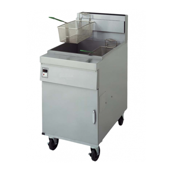
Decathlon series gas fryer
Hide thumbs
Also See for CFD:
- Installation & operation manual (52 pages) ,
- Service & parts manual (102 pages)
Table of Contents
Troubleshooting

Subscribe to Our Youtube Channel
Related Manuals for Dean CFD


Summary of Contents for Dean CFD
- Page 1 D, CFD, SCFD, FPD, and Common Cabinet Models NON-CE & Dean, a member of the Commercial Food Equipment Service Association, recommends using CFESA Certified Technicians. FEBRUARY 2007 *8195922* 24-Hour Service Hotline 1-800-551-8633...
- Page 2 If, during the warranty period, the customer uses a part for this Enodis equipment other than an unmodified new or recycled part purchased directly from Frymaster and Dean, or any of its authorized service centers, and/or the part being used is modified from its original configuration, this warranty will be void.
- Page 3 The front ledge of the fryer is not a step. Do not stand on the fryer. Serious injury can result Drawings and photos used in this manual are intended to illustrate operational, cleaning and technical procedures and may not conform to on-site management operational procedures.
-
Page 4: Table Of Contents
Oil Drain Manifold Components...2-20 Oil Return Manifold Components...2-24 Oil Return and Oil Flush Components...2-28 Under Fryer Filter (UFF) Components; D50 and D60 Series...2-32 Single Under Fryer Filter (SUFF) Components...2-37 2.10 Basket Lift Components; D50, D60, and D80...2-41 2.11 Trough, Holster, and Cover Components; D60 and D80 Series...2-43... - Page 5 FINDING YOUR WAY AROUND THE DEAN DECATHLON Basket Hanger Flue Cap Frypot Top Cap Electronic Operating Thermostat Burners Drain Tubes Drain Valve Handle (Red) Filter Unit Oil Return Handle (Yellow) Drain Flush Handle (Blue) Drain Tubes...
-
Page 6: Chapter 1: Service Procedures
DECATHLON SERIES GAS FRYERS CHAPTER 1: SERVICE PROCEDURES 1.1 Functional Description Decathlon Series gas fryers contain a welded steel frypot (stainless or cold-rolled) heated by gas flames diffused evenly through tubes built into the frypot. Flames originate from orifices in a burner manifold positioned beneath cast-iron burners. The burners are positioned in the tube openings, at the front of the frypot. - Page 7 The pilot flame must be manually lit when the fryer is first placed into operation. A separate 120V circuit, activated by the fryer ON/OFF switch, provides voltage through the Thermatron to the gas valve main coil, which opens the main valve.
- Page 8 Thermatron, or Compu-Fry computers. In fryers equipped with Thermatron, the fryer is turned on and off by means of a rocker switch and the temperature is set by adjusting a potentiometer. An interface board is located in the component box (shield) behind the control panel (computer-equipped) or in a component box inside the cabinet (Thermatron-equipped).
- Page 9 CHAPTER 1: SERVICE PROCEDURES Interface Boards The interface board provides a link between the controller/computer and the fryer’s individual components without requiring excessive wiring, and allows the controller to execute commands from one central point. Two types of interface boards may be used in Decathlon Series gas fryers;...
- Page 10 DECATHLON SERIES GAS FRYERS CHAPTER 1: SERVICE PROCEDURES Interface Boards (cont.) IFB 106-6669 & 106-6710: These interface boards are used in Decathlon fryers with Frymaster computer control systems. INTERFACE BOARD P/N 106-6669 FREQUENTLY USED TEST POINTS FOR INTERFACE BOARD P/N 806-4549 (previous style)
- Page 11 DECATHLON SERIES GAS FRYERS CHAPTER 1: SERVICE PROCEDURES Interface Boards (cont.) P/N 806-4549 INTERFACE BOARD (previous style) Indicates 12 VAC from transformer Indicates 24 VAC from transformer Indicates 24 VAC to gas valve Indicates 24 VAC to PWR via K1 (L) or K2 (R or F) Not Applicable to Decathlon Series Gas Fryers The board contains two heat relays (K2 and K3), and two basket lift relays (K1 and K4).
-
Page 12: Accessing Fryers For Servicing
4. After servicing is complete, reconnect the unit to the gas supply, reattach restraining devices, and plug in the electrical cords. No structural material on the fryer should be altered or removed to accommodate placement of the fryer under a hood. Questions? Call the Frymaster Dean Service DANGER relocate a fryer for servicing. - Page 13 When the fryer is leveled in its final position, install the restraints provided with the unit to limit its movement so that it does not depend on or transmit stress to the electrical conduit or connection.
-
Page 14: Cleaning The Gas Valve Vent Tube (If Applicable)
3. Insert the manometer fitting into the pressure tap hole. 4. Place the gas valve in the ON position then place the fryer power switch in the ON position. When the burner lights and continues to burn, check the gas pressure reading against the table on page 1-1. -
Page 15: Adjusting The Pilot Flame
2. Ensure the fryer ON/OFF switch is in the OFF position and light the pilot. 3. Place the fryer ON/OFF switch in the ON position. Set the electronic thermostat dial to 325°F (162°C). - Page 16 If necessary, stir to get all shortening in the bottom of the frypot melted. 5. Insert a thermometer or pyrometer probe into the oil, with the end near the fryer temperature- sensing probe. NOTE: The temperature-sensing probe is mounted on the frypot tube.
-
Page 17: Replacing Fryer Components
2. Unscrew the two computer panel screws. The computer panel is hinged at the bottom and will swing open from the top. 3. Unplug the fryer wiring harness and ground wire from the back of the computer. 4. Remove the computer by lifting it from the hinge slots in the fryer control panel frame. - Page 18 4. Disconnect the wiring plug(s) from the component shield/control box. 5. Disconnect leads from terminal block. 6. Remove screws securing the thermostat bracket to fryer. 7. Follow Steps 5-7 in Section 1.7.4, Replacing the High-limit Thermostat, to remove thermostat from frypot.
- Page 19 1. Disconnect the fryer from the electrical supply. 2. Drain cooking oil from the frypot. Allow the frypot to cool completely before proceeding. 3. Remove the fryer door for easier access to the temperature probe. D models: Lift door up, disengage rod from lower door bracket, and remove door.
- Page 20 20-22 on page 1-27 for more details.) NOTE: Ensure that the burners are placed in their original spots when putting them back into the fryer. (See page 1-28.) 7. Loosen and unscrew the compression nut and the pass-through nut completely from the frypot.
- Page 21 2. Perform steps 1-4 in Section 1.7.1, Replacing the Computer. 3. Remove the fryer door for easier access to the temperature probe. D models: Lift door up, disengage rod from lower door bracket, and remove door. CFD/SCFD/FPD models: Remove the top bracket and hinge, then remove door.
- Page 22 Newer pots will use mounting clips. Retain mounting hardware for installation of new high-limit. Newer pots have mounting clips. (cont.) Remove screws (arrows) securing high-limit to fryer. Compression nut unscrewed. Unscrew the pass-through nut (arrow) Older pots use spring-bracket combination. 1-17...
- Page 23 DECATHLON SERIES GAS FRYERS CHAPTER 1: SERVICE PROCEDURES 1.7.4 Replacing the High-limit Thermostat 7. Carefully pull high-limit capillary tube and bulb out of the frypot from the bottom. 8. Mark and disconnect wires at the high-limit in the component box. (cont.) Remove high-limit capillary tube and bulb from the bottom of the frypot.
- Page 24 1. Disconnect the fryer from the electrical supply. 2. If the switches are located on front panel, remove the screws securing panel to fryer. Do not allow the panel to hang on the switch wiring harness; use some type of support. (Figure A) If the switches are located in a control box within the fryer, remove the screws securing the switch panel to the control box.
- Page 25 1.7.6 Replacing the Gas Valve Drain the frypot or remove the handle from the drain valve before proceeding further. 1. Disconnect fryer from electrical and gas supplies. 2. Disconnect the wires from the gas valve terminal block, marking each wire to facilitate reconnections.
- Page 26 3. Unplug fryer from electrical supply source. 4. Remove the fryer door for easier access to the temperature probe. D models: Lift door up, disengage rod from lower door bracket, and remove door. CFD/SCFD/FPD models: Remove the top bracket and hinge, then remove door.
-
Page 27: Replacing The Frypot
7. Locate all screws securing back panels. Screw location and orientation will vary according to fryer model. 8. Remove back panels on fryer. Retain screws for re- assembly. 9. Remove screw securing brace (and back panel) to flue cap. - Page 28 (Step 16). Use a screwdriver or similar tool to free flue cap from frypots. Remove flue cap by lifting up and off of fryer. 11. Remove gas manifold pipe for access to gas manifold shield by disconnecting at the unions.
- Page 29 DECATHLON SERIES GAS FRYERS CHAPTER 1: SERVICE PROCEDURES 1.7.8 Replacing the Frypot 13. Remove steel line from oil-return valve and nipple by loosening flare fittings on both ends. Hold backup with an adjustable wrench when removing fittings. (Prior to removal, absorbent cloth or paper towels should be placed under the oil line to catch any oil remaining in the lines.) 14.
- Page 30 DECATHLON SERIES GAS FRYERS CHAPTER 1: SERVICE PROCEDURES 1.7.8 Replacing the Frypot 18. If fryer is equipped with a front drain manifold, disconnect manifold at slip-nut fitting and remove. 19. a. 1.5” drains: Remove drain extension from elbow on drain valve. Drain extensions will vary in shape and size according to fryer model.
- Page 31 NOTE: Current production units do not require removal of trailing pilot when removing burners. (cont.) Loosen burner Loosening burner bolts prior to burner removal. Removing burners from fryer. Old-style trailing pilot bracket is mounted on burners. 1-26...
- Page 32 DECATHLON SERIES GAS FRYERS CHAPTER 1: SERVICE PROCEDURES 1.7.8 Replacing the Frypot (cont.) Each burner is unique in the flame-transfer-hole configuration and must be reinstalled correctly: Left burners (L): Flame transfer hole is on the right side of the burner head. Center burners (C): Flame transfer hole is on both sides of the burner head.
- Page 33 DECATHLON SERIES GAS FRYERS CHAPTER 1: SERVICE PROCEDURES 1.7.8 Replacing the Frypot 23. Remove screw(s) securing the electronic or standing pilot bracket to the frypot bracket. Reposition ignitor assembly down and away from frypot. Use care not to bend, kink, or damage the electronic ignition lines and wiring.
- Page 34 Probe: Computer –equipped Fryers, for specific instructions.) 28. Remove the high-limit and backup thermostats. Follow Steps 5-7, Section 1.7.4, Replacing the High-limit Thermostat, and Section 1.7.2, Replacing Backup Thermostat, (where applicable) from frypot. 29. If the fryer is equipped with drain-valve microswitches, mark wires...
- Page 35 (two-vat or more). Use care not to scratch stainless steel surfaces. 32. Remove frypot from fryer by lifting up and out. 33. Position the frypot upside down on a suitable work surface.
-
Page 36: Troubleshooting And Problem Isolation
Ignition failure occurs when the ignition module fails to sense a flame within the 60-second time delay period and locks out. Turn the fryer off, locate and fix the problem, then turn fryer back on to clear the module lock. - Page 37 CE or Non-CE requirements listed in the Installation and Operation manual that came with the fryer, and that the pressure remains constant throughout all hours of usage. Refer to Adjusting Burner Manifold Pressure in Section 1.4 if burner manifold pressure is suspected of being incorrect.
- Page 38 CHAPTER 1: SERVICE PROCEDURES 1.8.2 Improper Burner Function If the fryer’s gas and air supplies are okay, the problem most likely is with one of the electrical components. Examine the ignition module for signs of melting, distortion, or discoloration due to excessive heat build-up in the fryer.
- Page 39 The principal component is the temperature probe. Depending upon the specific configuration of the fryer, other components may include the interface board, the computer/controller itself, and the ignition module. Improper temperature control problems can be categorized into melt cycle problems and failure to control at setpoint.
- Page 40 If the pump motor does not start, press the red reset switch located on the rear of the motor. Also, reset the filter circuit breaker located under the fryer control panel. If the pump then starts, something caused the motor to overheat. The pump most likely overheated for one of the following reasons: •...
- Page 41 DECATHLON SERIES GAS FRYERS CHAPTER 1: SERVICE PROCEDURES 1.8.5 Improper Filtration Function Incorrectly sized or installed paper will allow food particles and sediment to pass through and clog the suction tube on the bottom of the filter carriage. Particles large enough to block the suction tube may indicate that the crumb tray is not being used.
- Page 42 DECATHLON SERIES GAS FRYERS CHAPTER 1: SERVICE PROCEDURES 1.8.7 Improper Basket Lift Function Bell-Crank Basket Lifts Most Decathlon Series gas fryers are equipped with a bell- crank style basket lift. A cam and a bell crank are connected to the basket lift arm by a flat metal link. The cam is attached to a drive motor.
- Page 43 DECATHLON SERIES GAS FRYERS CHAPTER 1: SERVICE PROCEDURES 1.8.7 Improper Basket Lift Function Modular Basket Lifts Older Decathlon Series fryers may be equipped with modular basket lifts. basket lift consists of a notched rod to which the basket lift arm is attached, a reversible- drive gear motor, and a pair of roller-activated microswitches.
-
Page 44: Troubleshooting Guides
DECATHLON SERIES GAS FRYERS CHAPTER 1: SERVICE PROCEDURES 1.8.7 Improper Basket Lift Function Electronics failure. This category encompasses problems with the relays, microswitches, capacitors, resistors, interface board, wiring, and controls. Troubleshooting the electronics of the modular basket lift is simply a process of verifying current flow through the components up to and including the motor. - Page 45 DECATHLON SERIES GAS FRYERS CHAPTER 1: SERVICE PROCEDURES Troubleshooting Guides A. Pilot does not stay lit (fryer is on and thermopile output is approximately 400 millivolts and/or thermocouple is approximately 25 millivolts. B. Pilot does not stay lit (fryer is on and...
-
Page 46: Wiring Diagrams
DECATHLON SERIES GAS FRYERS CHAPTER 1: SERVICE PROCEDURES 1.10 Wiring Diagrams Note: The diagrams in this section depict wiring as of the date of manual publication. It may not reflect design changes made to the equipment after publication. Refer to the wiring diagram affixed to the unit when actually troubleshooting this equipment. - Page 47 DECATHLON SERIES GAS FRYERS CHAPTER 1: SERVICE PROCEDURES Decathlon, Dual Vat 1-42...
- Page 48 DECATHLON SERIES GAS FRYERS CHAPTER 1: SERVICE PROCEDURES Thermatron, 24V 1-43...
- Page 49 DECATHLON SERIES GAS FRYERS CHAPTER 1: SERVICE PROCEDURES Thermatron, 120V 1-44...
- Page 50 DECATHLON SERIES GAS FRYERS CHAPTER 1: SERVICE PROCEDURES Transformer Box 1-45...
- Page 51 DECATHLON SERIES GAS FRYERS CHAPTER 1: SERVICE PROCEDURES Decathlon Interface Board 1-46...
- Page 52 DECATHLON SERIES GAS FRYERS CHAPTER 1: SERVICE PROCEDURES Dean Oil Return Wiring 1-47...
- Page 53 DECATHLON SERIES GAS FRYERS CHAPTER 1: SERVICE PROCEDURES Single Decathlon with SUFF Filtration and Basket Lifts (PBI) THERMOCOUPLE 1-48 BLUE...
- Page 54 DECATHLON SERIES GAS FRYERS CHAPTER 1: SERVICE PROCEDURES Oil Return, Left-hand, Normally Open Float Switch 1-49...
- Page 55 DECATHLON SERIES GAS FRYERS CHAPTER 1: SERVICE PROCEDURES Basket Lift, with Timer 1-50...
- Page 56 DECATHLON SERIES GAS FRYERS CHAPTER 1: SERVICE PROCEDURES CM4-S with Constant Pilot 1-51...
- Page 57 DECATHLON SERIES GAS FRYERS CHAPTER 1: SERVICE PROCEDURES Chili’s Wiring Diagram 1-52...
- Page 58 DECATHLON SERIES GAS FRYERS CHAPTER 1: SERVICE PROCEDURES Chili’s Wiring with SCF Filtration 1-53...
-
Page 59: Chapter 2: Parts List
DECATHLON SERIES GAS FRYERS CHAPTER 2: PARTS LIST 2.1 Decathlon Primary Components Controllers, probes, and related components are listed in Optional Components and Controllers, Section 2.3. -
Page 60: Decathlon D20 Primary Components
DECATHLON SERIES GAS FRYERS Parts are labeled to indicate the appropriate fryer model (“D”, “SCFD”, “CFD”, or “FPD65”). If a part is not labeled, it can be used on any of these models. Each section is labeled by size (e.g., D50) and parts are not interchangeable between different sized fryers. -
Page 61: Decathlon D50 Primary Components
PART # 826-1871 Frypot - S/S (SCFD50, CFD50) 826-1873 Frypot - S/S (D50) 826-1869 Frypot - S/S, (DD50 Deep Depth, used in fryer batteries with D60) * Not illustrated. CHAPTER 2: PARTS LIST (cont.) COMPONENT ⁄ " Slotted Head (use with 810-2105) ⁄... - Page 62 DECATHLON SERIES GAS FRYERS 2.1.2 Decathlon D50 Primary Components ITEM PART # 826-2037 Frypot, Cracker Barrel (1.5” Drain) 810-2169 Manifold, Gas (D50) 810-2130 Manifold, Gas (SCFD50) 810-2048 Orifice, Natural Gas #39 2.53 mm (non-CE D50GHP, SCFD50G) 810-2062 Orifice, Natural Gas #38, 2.58 mm 810-2059 Orifice, LP/G31 Gas #53, 1.51 mm (CE, D50;...
- Page 63 200-2872 Shield, Flue Heat 200-1343 Front, Flue Box 200-1350 Rear, Flue Box 200-3651 Deflector, Flue 823-3521 Flue Cap, D50/CFD & 15MC (Single) 106-1754SP Door Assembly (D50) 210-2869 Panel, Outer Door 200-1379 Panel, Inner Door 106-4727 Door Assembly, Left (SCFD50) 106-4728...
-
Page 64: Decathlon D60 Primary Components
DECATHLON SERIES GAS FRYERS 2.1.2 Decathlon D50 Primary Components ITEM PART # 812-1717 Drain Nipple, Extended 1½” Drain 106-0913SP Cordset, 10' Power 210-2804 Cover, Outlet Duct 200-1674 Back Panel, Lower (D50/CFD50) 810-2411 Leg, Single Bolt Mount (black) 806-3811 Leg Package, 4 Bolt Mount (4 per set) 823-3248 Leg Support Assembly 200-1329... - Page 65 DECATHLON SERIES GAS FRYERS 2.1.3 Decathlon D60 Primary Components ITEM PART # 200-1363 Heat Shield, Lower (SCFD60) 824-0970 Heat Shield, Vessel (SCFD60) 812-0211 Insulation, Kaowool Blanket, .5” x 7.5” x 17.5” 824-0969 Support, Burner 807-3552 Gas Valve, Natural Gas, Electronic Ignition, 24 VAC (¾” in, ½” out) 807-3628 Gas Valve, LP Gas, Electronic Ignition, 24 VAC 807-3294...
- Page 66 DECATHLON SERIES GAS FRYERS 2.1.3 Decathlon D60 Primary Components ITEM PART # 106-1703SP Flue Cap (Single) 823-3516 Flue Cap (2-battery) 106-2898SP Door Assembly, with Liner (D60) 200-1185 Panel, Door, Inner 210-1424 Panel, Door, Outer 106-4721 Door Assembly, Left (SCFD60) 200-4794 Panel, Door, Inner 211-8935 Panel, Door, Outer...
- Page 67 DECATHLON SERIES GAS FRYERS 2.1.4 Decathlon FPD65 Primary Components ITEM PART # 823-3948SP Frypot - S/S 812-1666 Coupling, Thermostat Entry 813-0036 Collar, Thermostat 210-1650 Deflector, Oil Return 812-1501 Nipple, 1 810-2072 Gas Manifold (weld assembly) 810-2048 Orifice, Natural Gas #39 2.53 mm (non-CE) 810-2059 Orifice, LP Gas #53 1.51 mm (CE and non-CE) 810-2497...
- Page 68 DECATHLON SERIES GAS FRYERS 2.1.4 Decathlon FPD65 Primary Components ITEM PART # 212-4570 Side Panel, Right Side (unit exterior) 201-4775 Side Panel, Left Side with Hole (unit interior) 202-4775 Side Panel, Right Side with Hole (unit interior) 201-4237 Panel, Inner Left (divider located over filter unit) 202-4237 Panel, Inner Right (divider located over filter unit) 824-1195...
-
Page 69: Decathlon D80 Primary Components
DECATHLON SERIES GAS FRYERS 2.1.4 Decathlon FPD65 Primary Components ITEM PART # 812-1226SP Drain Nipple, Extended 106-0913SP Cordset, 10’ Power 210-2804 Cover, Outlet Duct 200-1213 Upper Structural Back 200-1327 Lower Structural Back 810-2411 Leg, Single Bolt Mount (black) 806-3811 Leg Package, 4 Bolt Mount (4 per set) 823-3248 Leg Support Assembly 200-2065... - Page 70 DECATHLON SERIES GAS FRYERS 2.1.5 Decathlon D80 Primary Components ITEM PART # 810-2151 Burner, Left Side 810-2149 Burner, Center 810-2150 Burner, Right Side 200-2707 Heat Shield 200-1363 Lower Heat Shield 807-3552 Gas Valve, Natural Gas Electronic Ignition, 24 VAC 807-3628 Gas Valve, LP Gas Electronic Ignition, 24 VAC 810-2156 Gas Valve, Natural Gas, 120 VAC...
- Page 71 DECATHLON SERIES GAS FRYERS 2.1.5 Decathlon D80 Primary Components ITEM PART # 210-9889 Pin, Door (SCFD80) 810-0066 Magnetic Catch, Door (D80) 810-1105 Magnetic Catch, Door (SCFD80) 803-0304 Fry Basket, 6 x 8 810-2122 Grid Assembly (mesh-style) 803-0300 Grid Assembly (rack-style) 200-3120 Hanger, Basket, Single System, M/S (D80) 210-2887...
- Page 72 DECATHLON SERIES GAS FRYERS 2.2 Control Panel Options, Joiner Strips, and Accessories ITEM PART # 210-3562 210-3021 210-6405 210-2051 210-4672 210-5061 210-5910 210-3910 210-1256 210-8552 230-2146 106-5909 230-1948 230-2149 106-5927 106-6332 211-6640 212-6640 210-4847 211-4816 212-4816 210-3327 210-3017 210-1679 823-3938 106-2631SP 823-3947 * Not illustrated.
-
Page 73: Optional Components And Controllers
DECATHLON SERIES GAS FRYERS 2.3 Optional Components and Controllers ITEM PART # 826-2013 810-2035 826-2117 807-3484 807-1311 807-1553 807-1315 810-0705 807-1310 * Not illustrated. CHAPTER 2: PARTS LIST COMPONENT Thermostat, Sunne Knob, Thermostat Spark Module, Domestic and CE (Rajah Connector, 807-3484) Rajah Connector (for Blue/Gray Honeywell module, 807-4037, no longer avail.) Pilot Assembly, Natural Gas with Electronic Ignition Pilot Assembly, LP Gas with Electronic Ignition... - Page 74 807-3750 * Not illustrated. CHAPTER 2: PARTS LIST (cont.) COMPONENT Brush, L-shaped Fryer’s Friend Gloves Pilot Assembly (w/computer and electronic ignition), Natural Pilot Assembly (w/computer and electronic ignition), LP Pilot Assembly (without computer), Natural Air Shutter Kit See Control Panel Options, Section 2.2 Computer, Compu-Fry III.5, Full-vat...
- Page 75 Relay, 12VDC 15A 1PDT (basket lift) Relay, 12VDC 5A 1PDT (latching) Relay, 24VAC Coil, Reset Switch, Power (green lens) Switch, Rocker, Manual Filter Power Switch, Six-terminal Boil-out Switch, Fryer Reset (momentary) Switch, 3-position, ON-OFF-ON Indicator Light, Green Indicator Light, Red Pump Relay Socket, Pump Relay...
-
Page 76: Transformers And Component Boxes; Multi-Batteried Decathlon
DECATHLON SERIES GAS FRYERS CHAPTER 2: PARTS LIST 2.4 Transformers & Component Boxes; Multi-batteried Decathlons 2-18... - Page 77 DECATHLON SERIES GAS FRYERS 2.4 Transformers & Component Boxes; Multi-batteried Decathlons ITEM PART 823-3242 Control Box (D50/CFD50/SCFD50) 106-2691 Control Box (FPD65) 210-1364 Plate, Face (for Item 1) 210-2966 Plate, Face (for Item 1, FPD65) 200-1322 Bracket, Spark Module 200-1326 Cover, Spark Module (Fryers 3 & 4) 200-2307 Bracket, Spark Module Attachment (Fryers 1 &...
-
Page 78: Oil Drain Manifold Components
DECATHLON SERIES GAS FRYERS Some Decathlon series fryers are equipped with 3” round drain systems while others are equipped with 1.5” round drain systems. Compare the fryer in question with the illustrations on pages 2-20 to 2-23 to determine which system it uses. - Page 79 DECATHLON SERIES GAS FRYERS 2.5.1 1.5” Oil Drain Manifold, Drain Flush, and Drain Valve Components ITEM PART # 823-3221 823-3222 823-5167 210-2311 823-4931 813-0749 200-5621 200-1827 813-0659 813-0391 813-0748 809-0884 816-0544 813-0686 810-1057 813-0051 813-0165 810-1668 810-1669 810-1069 806-6849 106-1401 200-1617 210-2029 210-4727...
- Page 80 DECATHLON SERIES GAS FRYERS 2.5.2 3” Oil Drain Manifold, Drain Flush, and Drain Valve Components ITEM PART # 823-4712 812-1901 823-5912 823-4681 823-6079 823-4844 823-4680 CHAPTER 2: PARTS LIST COMPONENT Tube, 3" Oval Dump Tube, 3" Downspout Tube, 3" Off-set Downspout Tube, 3"...
- Page 81 DECATHLON SERIES GAS FRYERS 2.5.2 3” Oil Drain Manifold, Drain Flush, and Drain Valve Components ITEM PART # 823-6076 Tube, 3" Left Drain (3.86" long, closed end) 200-9365 Tube, 3" Joiner (9.13" long, open ends) 823-4682 Tube, 3" Center Drain (8” long, open ends) 200-6603 Tube, 3"...
-
Page 82: Oil Return Manifold Components
DECATHLON SERIES GAS FRYERS Decathlon series fryers differ in oil return configuration. Compare the fryer in question with the illustrations on pages 2-24 to 2-31 to determine which system it uses. 2.6 Oil Return Manifold Components 2.6.1 Oil Return Manifold Components; D & FPD65 Models... - Page 83 DECATHLON SERIES GAS FRYERS 2.6.2 Oil Return Manifold Components; SCFD, CFD, & FPD65 Models ITEM PART # 106-4100 106-4101 106-6763 106-5616 810-3117 810-3115 106-4006 106-3997 106-5516 106-5231 810-1668 810-2320 813-0003 813-0022 813-0096 813-0165 813-0173 813-0247 813-0362 813-0463 813-0661 813-0654 813-0597...
-
Page 84: Oil Return And Oil Flush Components
813-0673 813-0698 * Not illustrated. Decathlon series fryers differ in oil return configuration. Compare the fryer in question with the illustrations on pages 2-24 to 2-31 to determine which system it uses. 2.7 Oil Return and Oil Flush Components 2.7.1 Oil Return and Oil Flush Components; D & FPD65 Models... - Page 85 Cotter Pin, Plated Handle (Actuator), Oil Return Valve Handle, Oil Return Left Fryer (UFF System) Handle, Oil Return Right Fryer (UFF System, Fryer 3 & 4) Handle, Oil Flush Valve Cap, Drain Valve Handle, Red Cap, Oil Return Handle, Yellow...
-
Page 86: Oil Return And Oil Flush Components
DECATHLON SERIES GAS FRYERS 2.7.2 Oil Return and Oil Flush Components; SCFD, CFD, & FPD65 Models CHAPTER 2: PARTS LIST 2-28... - Page 87 DECATHLON SERIES GAS FRYERS 2.7.2 Oil Return and Oil Flush Components; SCFD, CFD, & FPD65 Models ITEM PART # 106-4006 901-2772 900-2935 816-0220 810-0278 826-1366 807-2103 200-6806 106-3962 106-1225SP 813-0062 813-0173 813-0654 813-0674 200-1230 106-1720 813-0062 813-0173 813-0093 813-0741 200-1230...
- Page 88 DECATHLON SERIES GAS FRYERS 2.8 UFF Filtration Components 2.8.1 UFF Filtration Components; D50 Series Fryers ITEM PART # 106-2115SP 809-0805 809-0428 809-0820 823-4794 810-2805 823-3574 803-0289 823-3573 823-4320 106-0752SP 106-1755SP 106-3230SP 106-2568SP * Not illustrated. CHAPTER 2: PARTS LIST COMPONENT Filter Pan Screw, ¼-20 x ½"...
- Page 89 DECATHLON SERIES GAS FRYERS 2.8.2 UFF Filtration Components; SCFD50 Series Fryers ITEM PART # 106-5144SP 823-5639 823-3573 823-5191 200-8003 810-2805 809-0823 813-0568 803-0170 * Not illustrated. CHAPTER 2: PARTS LIST DESCRIPTION Filter Pan Lid, Filter Pan Ring, Hold Down Crumb Basket Screen, Sana Grid Caster, 2”...
- Page 90 DECATHLON SERIES GAS FRYERS 2.8.3 UFF Filtration Components; D60 and D80 Series Fryers ITEM PART # 106-0749SP 106-1584SP 106-4521 823-3365 803-0289 803-0303 823-3361 823-3439 823-4320 823-3443 106-0752SP 106-1587SP 106-0753SP 106-1588SP 809-0428 823-4794 809-0820 809-0805 210-2805 * Not illustrated. CHAPTER 2: PARTS LIST COMPONENT Filter Pan (UFF 60) Filter Pan (UFF 80)
- Page 91 DECATHLON SERIES GAS FRYERS 2.8.4 UFF Filtration Components; SCFD60 and FPD65 Series Fryers ITEM PART # 106-1220SP 823-4109 106-4725SP 106-6119SP 823-4320 823-3872 823-3361 810-2350 200-5726 810-2582 810-2805 809-0070 803-0289 * Not illustrated. CHAPTER 2: PARTS LIST COMPONENT Filter Pan (SCFD) Filter Pan (FPD) Lid Assembly (SCFD) Lid Assembly (FPD)
- Page 92 DECATHLON SERIES GAS FRYERS 2.8.5 UFF Filtration Components; SCFD80 Series Fryers ITEM PART # 823-5406 106-5321 106-5317 823-5412 823-5409 823-3365 810-2805 823-5407 809-0804 809-0191 809-0428 813-0679 813-0704 803-0303 * Not illustrated. CHAPTER 2: PARTS LIST COMPONENT Filter Pan Lid, Front (UFF 80) Lid, Rear (UFF 80) Crumb Basket Hold Down Ring...
- Page 93 DECATHLON SERIES GAS FRYERS 2.9 SUFF Filtration Components 2.9.1 SUFF Filtration Components; D50 Series Fryers ITEM PART # 823-3796 813-0684 813-0679 823-3790 803-0317 823-3795 823-3736 823-3797 823-3798 809-0428 823-4794 809-0820 809-0805 810-2805 * Not Illustrated. CHAPTER 2: PARTS LIST COMPONENT Filter Pan (SUFF 50) Plug, Hex Socket, 3/8"...
- Page 94 DECATHLON SERIES GAS FRYERS 2.9.2 SUFF Filtration Components; CFD50 Series Fryers ITEM PART # 823-3796 823-3798 823-3797 823-3795 823-5423 823-3790 803-0317 810-2805 823-5407 809-0804 809-0428 809-0191 813-0679 * Not Illustrated. CHAPTER 2: PARTS LIST COMPONENT Filter Pan Lid, Filter Pan, Rear Lid, Filter Pan, Front Hold-down Ring Crumb Basket (SUFF50/60/80)
- Page 95 DECATHLON SERIES GAS FRYERS 2.9.3 SUFF Filtration Components; D60 and D80 Series Fryers ITEM PART # 823-3774 823-3821 813-0684 813-0679 823-3768 803-0289 823-3770 823-3849 823-3736 823-3766 823-3739 823-3767 823-3741 809-0428 823-4794 809-0820 809-0805 810-2805 * Not Illustrated CHAPTER 2: PARTS LIST COMPONENT Filter Pan (SUFF 60) Filter Pan, (SUFF 80)
- Page 96 DECATHLON SERIES GAS FRYERS 2.9.4 SUFF Filtration Components; CFD60 and CFD80 Series Fryers ITEM PART # 823-5420 823-3821 106-1433 823-5424 823-3739 823-5425 823-3741 823-5422 823-3849 823-5423 823-5421 809-0428 813-0679 809-0804 809-0191 810-2805 823-5407 803-0289 813-0684 * Not Illustrated. CHAPTER 2: PARTS LIST COMPONENT Filter Pan (SUFF 60) Filter Pan (SUFF 80)
- Page 97 DECATHLON SERIES GAS FRYERS CHAPTER 2: PARTS LIST 2.10 Basket Lift Components; D50, D60, and D80 Models … 2-39...
-
Page 98: Basket Lift Components; D50, D60, And D80
DECATHLON SERIES GAS FRYERS 2.10 Basket Lift Components; D50, D60, and D80 Series Fryers ITEM PART # 106-1914 106-1870 106-1926 200-1376 200-2069 200-3094 200-2735 200-3072 809-0882 809-0907 809-0863 810-2140 813-0035 824-0996 824-0958 824-0990 824-0997 824-0959 824-0991 200-1693 807-0107 823-3626 807-2104 810-2144 809-0846 809-0842... - Page 99 CHAPTER 2: PARTS LIST COMPONENT Holster Assembly, Vat Cover Trough, Holster Assembly Cover, Full-vat Cover, Split-vat Cover, FPD Handle, Vat Cover (Full- and Split-) Screw, 8-32 x ⁄ " Round Slotted Head Splash Guard L-shaped Brush Fryer’s Friend Crumb Scoop 2-41...
- Page 100 Dean, 8700 Line Avenue, PO Box 51000, Shreveport, Louisiana 71135-1000 Shipping Address: 8700 Line Avenue, Shreveport, Louisiana 71106 TEL 1-318-865-1711 FAX (Parts) 1-318-688-2200 FAX (Tech Support) 1-318-219-7135 SERVICE HOTLINE PRINTED IN THE UNITED STATES 1-800-551-8633 819-5922 FEBRUARY 2007...
Need help?
Do you have a question about the CFD and is the answer not in the manual?
Questions and answers