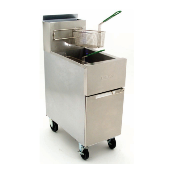
Dean Series SR52 Installation & Operation Manual
Series sr42, sr52 & sr62 super runner series gas fryers
Hide thumbs
Also See for Series SR52:
- Installation & operation manual (40 pages) ,
- Installation & operation manual (16 pages) ,
- Installation & operation manual (15 pages)
Table of Contents
Advertisement
Quick Links
Advertisement
Table of Contents

Subscribe to Our Youtube Channel
Related Manuals for Dean Series SR52


Summary of Contents for Dean Series SR52
- Page 1 Series SR42, SR52 & SR62 NON-CE & Price: $10.00 For Service, Call (318) 865-1711 MARCH 2008 Dean, 8700 Line Avenue, PO Box 51000, PRINTED IN THE Shreveport, Louisiana 71135-1000 UNITED STATES *8195999* Shipping Address: 8700 Line Avenue, Shreveport, Louisiana 71106...
- Page 2 The front ledge of the fryer is not a step! Do not stand on the fryer. Serious injury can result from slips or contact with the hot oil.
-
Page 3: Clearance And Ventilation
24-inches (600-mm) clearance should be provided at the front of the fryer. The fryer flue opening must not be placed close to the intake of an exhaust fan, and the fryer must never have its flue extended in a "chimney" fashion. An extended flue will change the combustion characteristics of the fryer. To provide the airflow necessary for good combustion and burner operation, the areas surrounding the fryer front, sides, and rear must be kept clear and unobstructed. - Page 4 For units equipped with legs: Lift the unit and move it into its final position. Do not drag or push the fryer into position. Doing so may damage the legs. Level the unit front to back and side to side. If the fryer is not level, the unit will not function efficiently.
-
Page 5: Australian Requirements
Connection to the Gas Supply Line NOTE: The gas supply (service) line must be the same size or greater than the fryer inlet line. This appliance is equipped with a ½-inch (15- mm) inlet. The gas supply line must be sized to accommodate all gas- fired equipment connected to the line. - Page 6 Adequate means must be provided to limit the movement of fryers without depending upon the gas line connections. If a flexible gas hose is used, a restraining cable must be connected at all times when the fryer is in use. NOTE: The installation must be inspected after it is complete to ensure it meets the intent of these instructions.
- Page 7 SUPER RUNNER SERIES GAS FRYERS CHAPTER 1: INSTALLATION INSTRUCTIONS When converting from G20 (or G25) gas to G31 propane (or vice-versa), the following procedures apply: ♦ Burner orifices and pilot orifice MUST be replaced. ♦ Adjust orifice gas pressure to the appropriate value listed in the table on page 1-3 by turning the gas-valve adjustment screw.
-
Page 8: Gas Conversion Components
SUPER RUNNER SERIES GAS FRYERS CHAPTER 1: INSTALLATION INSTRUCTIONS Manifold Support Bracket Gas Burner See Detail A Orifice Pressure Test Spigot Assembly Temperature Control Typical gas valve, burner and orifice locations (SR42 shown above). 1.6 Gas Conversion Components Use the following components to convert from natural gas to propane and vice- versa. -
Page 9: Chapter 2: Operation
2.1.2 Pilot Lighting Procedures NOTE: This fryer was tested, adjusted and calibrated to sea level conditions before leaving the factory. Adjustments may be necessary to meet local conditions, and are to be performed only by qualified service personnel. Adjustments are the responsibilities of the customer or dealer and are not covered by Dean warranty. - Page 10 7. Open the manual shut-off valve on the incoming service line. 8. Apply a lighted match or taper to the pilot burner head. (If fryer is equipped with a piezo ignitor, go to Step 9). 9. Press the white button on the gas valve and hold approximately 45 seconds to 1 minute, until the pilot stays lit. (If fryer is equipped with a piezo ignitor, press and hold the white button, then repeatedly press the piezo ignitor button until the pilot lights.
- Page 11 (Non-CE) or press the red button (CE) and cover the frypot. 2.3 Daily Operation 1. Do not allow grease to accumulate or harden on the frame, body, or flue of the fryer. Clean the fryer inside and out with a solution of detergent and hot water daily.
-
Page 12: Wiring Diagram
SUPER RUNNER SERIES GAS FRYERS 2.5 Wiring Diagram CE UNITS ONLY: NON-CE UNITS ONLY: CHAPTER 2: OPERATION WARNING DO NOT CONNECT ANY EXTERNAL ELECTRICAL POWER TO THIS UNIT OPERATING THERMOSTAT HIGH-LIMIT HONEYWELL CE CONTROL CIRCUIT PILOT GENERATOR ADJ. PILOT P.S.I. HONEYWELL PILOT 1/2 P.S.I. - Page 13 THIS PAGE INTENTIONALLY LEFT BLANK...
- Page 14 Dean, 8700 Line Avenue, PO Box 51000, Shreveport, Louisiana 71135-1000 Shipping Address: 8700 Line Avenue, Shreveport, Louisiana 71106 TEL 1-318-865-1711 FAX (Parts) 1-318-219-7140 FAX (Tech Support) 1-318-219-7135 Price: $10.00 PRINTED IN THE UNITED STATES 819-5999 MARCH 08...
Need help?
Do you have a question about the Series SR52 and is the answer not in the manual?
Questions and answers