Table of Contents
Advertisement
Quick Links
Advertisement
Table of Contents

Subscribe to Our Youtube Channel
Related Manuals for Millipore APC ErgoTouch Pro 2


Summary of Contents for Millipore APC ErgoTouch Pro 2
- Page 1 APC ErgoTouch Pro 2 Airborne Particle Counter Operation Manual...
-
Page 2: Returning The Apc Ergotouch Pro
MANUAL HISTORY The following is a manual history of the APC ERGOTOUCH PRO 2 Handheld Airborne Particle Counter Revision Date: January 2012 IMPORTANT NOTE In the following Merck shall mean Merck KGaA, Darmstadt, Germany. -
Page 3: Table Of Contents
Sample Timing Screen Caution or Warning Symbols Alarms Screen 1 Introduction and Unpacking Count Mode Screen Unpacking the APC ERGOTOUCH PRO 2 Handheld Count Units Screen Airborne Particle Counter Environment Screen Model APC ErgoTouch Pro 2 Airborne Particle Locations Screen... -
Page 4: Safety Information
Safety Information This section gives instructions to promote safe and proper handling of the APC ERGOTOUCH PRO 2 Handheld Airborne Particle Counters. IMPORTANT 4. Laser radiation There are no user-serviceable parts inside the instrument. label (internal) Refer all repair and maintenance to a qualifi ed factory- authorized technician. -
Page 5: Introduction And Unpacking
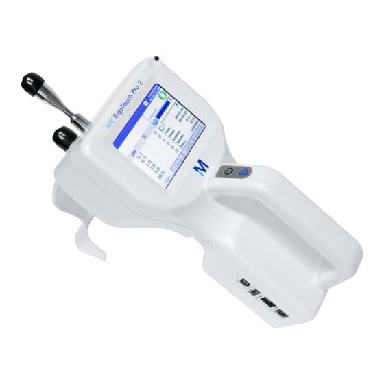
Unpacking the APC ERGOTOUCH PRO 2 Handheld Airborne Particle Counter Carefully unpack the APC ERGOTOUCH PRO 2 Airborne Particle Counter from the shipping container and verify that all the items shown in the photos below and listed in the following tables are present. Contact Merck KGaA, Darmstadt, Germany immediately if items are missing or broken. -
Page 6: Optional Accessories
Optional Accessories The following photos and table list optional accessories. If you ordered optional accessories, make certain they have been received and are in working order. Model APC ErgoTouch Pro 2 Airborne Particle Counter Optional Accessories Item Description Part/Model Reference Picture External battery charger with AC adapter 1.44134.0001... -
Page 7: Getting Started
2 Getting Started This chapter provides information to help you use the Model APC ErgoTouch Pro 2 Handheld Airborne Particle Counter including: • Instrument Description • Using the Instrument Stand and Stylus • Providing Power • Performing a Zero Check • Installing an Isokinetic Inlet... -
Page 8: Providing Power
To Use AC Power 1. Connect the AC power adapter to the power cord. 2. Insert the AC power adapter into the side of the Model APC ErgoTouch Pro 2 3. Connect the power cord to an outlet. 4. Press the on/off button (located on the front of the instrument handle). -
Page 9: Using With A Printer
Model 1.44163.0001 thermal printer (see Chapter 3, “Operation”). Only the Model 1.44305.0001 printer is compatible with the Model APC ErgoTouch Pro 2. The printer may be used on its internal battery or an AC adapter. A custom commu- nications cable is included with the printer. -
Page 10: Installing An Isokinetic Inlet
Installing an Isokinetic Inlet The Isokinetic inlet smoothly accelerates air into the inlet of the instrument. To install, simply thread the inlet directly onto the inlet nozzle until finger tight. The inlet seals over an O-ring so it doesn’t have to be very tight to seal. -
Page 11: Operation
3 Operation The Model APC ErgoTouch Pro 2 Handheld Airborne Particle Counter is controlled using a touch screen display. Use the plastic stylus or your finger tip. DO NOT use sharp objects (such as a pen point) that may damage the screen overlay. - Page 12 Icon Description Laser requires service Suffi cient fl ow through the APC APC ErgoTouch Pro 2 Insuffi cient fl ow through the APC APC ErgoTouch Pro 2 Operating on AC power, no battery installed Operating on AC power, battery is installed and charging.
-
Page 13: Zoomed Data Screen
Zoomed Data Screen The Zoomed Data screen is entered by touching in the size and count part of the main tab display. The bottom portion of the screen summarizes the concentrations for the currently selected location. Tap the size and count portion of the display to switch back to the Main Tab display. -
Page 14: System Setup Screen
System Setup Screen From the System Setup screen you can select (or change) the power on password, set up a password, select system configuration parameters, select print settings, schedule printing and clear samples. Change Power On Password Screen If a Power On password has been previously set, you must enter that password before being allowed to change the Power On password. -
Page 15: Change Setup Password Screen
Change Setup Password Screen If a Setup password has been previously set, you must enter that password before being allowed to change the Setup password. If a Setup password is set, click- ing on the setup tab at the bottom of the main screen brings up a password screen. -
Page 16: Print Setup Screen
Print Setup Screen A hard copy of a sample set or statistics can be printed from the instrument using an optional thermal printer. Use this screen to set print parameters. Press OK when finished. Field Description Serial Number Indicates that the serial number of the particle counter used to collect the data will be printed. -
Page 17: Clear Samples Screen
Clear Samples Screen The Clear Samples screen lets you clear all samples from the internal database. Select Yes to clear all samples. Select No to return to the System Setup screen. Device Setup Screen Use this screen to access screens that let you set or change the date and time, set visual parameters of the display, set up communications, set regional features, and get system information such as soft-... -
Page 18: Display Screen
Display Screen This screen lets you set or change visual parameters Field Description Screen Press this item to reset the screen Alignment alignment, and follow the directions on the alignment screen. Information Screen This screen lets you view the system’s model, serial number, copyright, manufacture date, calibration date, next calibration date, firmware version, USB IP address and date and time format. -
Page 19: Regional Screen
Regional Screen This screen lets you set the language in which the on-screen dialog is displayed and your regional format for numbers. Field Description Language Select the language in which you want on-screen dialog displayed; options are German, English, Spanish, French, Italian, Chinese, and Japanese. -
Page 20: Sample Timing Screen
This screen lets you select parameters for sampling. Use the up and down arrows or the on-screen key- board to change or enter information. These parame- ters are only valid when the APC APC ErgoTouch Pro 2 is running in Automatic mode. Press OK when finished. Field... -
Page 21: Count Mode Screen
Count Mode Screen Use this screen to set the sample count mode. Press OK when finished. Field Description Automatic If you select this mode, the APC APC Ergo Touch Pro 2 starts counting in automatic mode when you press the start button according to the settings on the Sample Timing Screen. Manual If you select this mode, the APC APC Ergo Touch Pro 2 starts sampling immediately when you press the start button and stops at the end of the sample time, which is confi gured on... -
Page 22: Environment Screen
Environment Screen Use this screen to set the units for temperature, which is displayed on the Main and Data Tabs, and the printouts when a humidity and temperature probe is hooked up to the instrument. Field Description °F Display temperature in degrees Fahrenheit. °C Display temperature in degrees Celsius. -
Page 23: Recipe Screen
Recipe Screen Use this screen to load and save recipes. Recipes let you save a group of settings (recipe) that you use over and over so you don’t have to reset individual settings. There may be up to 100 recipes stored in the unit. Field Description Save... -
Page 24: Data Tab
Data Tab The Data tab lets you preview data that has been collected. Use the elevator (slide) on the right to scroll though the records. The record number is displayed at the bottom of the tab. As each record displays, its data and relevant parameters are displayed. -
Page 25: Export Data Screen
Export Data Screen The export button lets you export sample data to a flash drive. The data will be exported in .XML format that can be opened in Microsoft Excel® spreadsheet (ver- sion 2003 or later) or other XML readers applications. Field Description Export If you select a name in the box (highlighted),... -
Page 26: Reports Tab
Reports Tab Use this screen to select various standard reports for viewing and printing. Use the Room Definition icon viewing and printing. Use the Room Definition icon to view or change specific values for the room to view or change specific values for the room and class, and the Generate icon to generate re- ports for viewing or printing. -
Page 27: Room Definition Screen
Room Definition Screen Use this screen to define specific values for the room. Press OK when finished. Field Description Room Status Select the room status: As Built, At Rest, or Operational. Air Flow Select the air fl ow: Unidirectional or Non-unidirectional. Class Select the class of the room: The class is dependent on the standard: FED FT3: 1, 20, 100,1000,10000, 100000... -
Page 28: Data Handling
4 Data Handling USB Data Download The Model APC ErgoTouch Pro 2 Handheld Airborne Particle Counter is equipped with a USB A host drive that will allow for the downloading of stored data to a USB Thumb drive. To download data, attach a thumb drive to the USB A host port and follow the instructions in the operation section of this manual. -
Page 29: Maintenance And Warranty
Maintenance Schedule We recommend annual factory cleaning and calibration for the APC ERGOTOUCH PRO 2 Airborne Particle Counter. See Chapter 7, “Contacting Customer Service” for service/calibration. Recommended Field Maintenance Schedule... -
Page 30: Troubleshooting
6 Troubleshooting Symptom Possible Cause Corrective Action Counts are too low. Instrument is being operated outside temperature or Operate instrument within specifi cations. relative humidity specifi cations. Internal parts have been damaged because instrument was Return to factory or factory authorized service centers stored at a temperature greater than 122°F (50°C). -
Page 31: Contacting Customer Service
• If the APC ErgoTouch Pro 2, does not operate properly, or if you are returning the instrument for service, visit our International Contacts Returning the APC Ergotouch Pro 2... -
Page 32: Appendix A - Specifications
APPENDIX A – Specifications All specifications meet or exceed ISO 21501-4 and JIS B9921. They are subject to change without notice. Size Range 0.3 to 10 µm Channel Sizes Standard: 0.3 to 10 µm, user-selectable; factory-calibrated at 0.3, 0.5, 1.0, 3.0, 5.0, 10.0 µm Size Resolution <15% at 0.5 µm (per ISO 21501-4 requirements) Counting Efficiency... -
Page 33: Temperature/Rh Probe (700084) Specifications (Optional Accessory)
Temperature/RH Probe (700084) Specifications (optional accessory) Temperature Range 32 to 115ºF (0 to 45ºC) Accuracy ±4ºF (±2ºC) Relative Humidity Range 10 to 90% RH Accuracy ±5% RH Compliance CE Marking EN61326 / EN 55011, Class BA: Radiated Emissions EN61326 / EN 55011, Class BA: Conducted Emissions EN61000-3-2: Harmonics EN61000-3-3: Voltage Fluctuations EN61000-4-2: Electrostatic Discharge Immunity... - Page 36 We provide information and advice to our customers on application technologies and regulatory matters to the best of our knowledge and ability, but without obligation or liability. Existing laws and regulations are to be observed in all cases by our customers. This also applies in respect to any rights of third parties.
Need help?
Do you have a question about the APC ErgoTouch Pro 2 and is the answer not in the manual?
Questions and answers