Table of Contents
Advertisement
Quick Links
Thank you for having purchased the Model VFK2560-8 class.
Before using your VFK2560-8 class, please read the instruction manual and
understand the contents well.
After reading the instruction manual, please keep it in a location where it is
easily accessible to the operator.
Instruction Manual
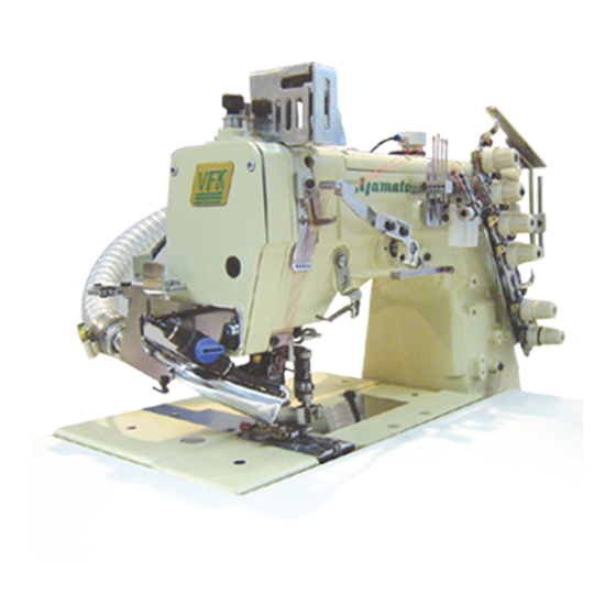
4 NEEDLE HIGH SPEED FLATBED FLATSEAMER
VFK2560-8
class
Advertisement
Table of Contents

Related Manuals for Yamato VFK2560-8


Summary of Contents for Yamato VFK2560-8
- Page 1 VFK2560-8 class Thank you for having purchased the Model VFK2560-8 class. Before using your VFK2560-8 class, please read the instruction manual and understand the contents well. After reading the instruction manual, please keep it in a location where it is...
-
Page 2: Table Of Contents
CONTENTS Safety instructions ⅰ - iv Name of each part Installation Semi-submerged type 2.1.1 Table cutting diagram 2.1.2 Installation 2.1.3 Installing supplimentary table Full-submerged type 2.2.1 Table cutting diagram 2.2.2 Installation Motor, pulley and belt Hanging belt Belt cover Thread guide plate Installing SC30 device Sewing speed and rotating direction of pulley Lubrication... - Page 3 CONTENTS 5.13 Adjusting the fabric lapping(both-side fabric edge trimming) 5.14 Adjusting SC30 device 5.15 HR device and SP device 5.16 Cleaning Adjustments Needle thread tension Top cover thread tension Looper thread tension 6.3.1 Looper thread tension 6.3.2 Position of looper thread take-up Height of presser foot Replacing presser foot spring plate Replacing and adjusting knives...
-
Page 4: Safety Instructions Ⅰ
(3) When carrying the sewing machine head, have Use the Yamato SF oil as specified. an assistant. (3) Never put your hand under the needle or near (4) Pay attention not to get excessive impact or... - Page 5 Safety instructions supply switch.) (4) When operating a new sewing machine, make (4) Be sure to remove the gasket too, when the sure the rotating direction of pulley agrees cover removed at the maintenance, inspec- with the rotating-direction mark. tion, and repair. If not removed, may be injured at the edge of gasket.
- Page 6 Safety instructions 4-2 Alert pictorial markings High-voltage applies in the control box. This label indicates This mark indicates the warning that electric shock which, if not heeded, could re- may be caused. sult in death or Serious injury. This label is affixed on the This mark indicates the caution safeguards.
- Page 7 Safety instructions Rotating direction symbol Knife mechanism 6. Other factor which may cause injury, precaution against it Knife mechanism As the knife trimming mechanism is moving to the right-and-left while sewing, if your hand holding the fabric comes close to the mechanism, your hand may be in danger of being struck or pinched in the gap below.
-
Page 8: Name Of Each Part
Needle thread take-up guard Thread tension Feed regulating pushbutton spring cap Side cover Looper thread take-up cover Oil sight gauge Front cover Differential feed graduation Lap former Supporting plate for looper Presser foot thread take-up HR cup Chip guard Fig. 1-1 VFK2560-8... -
Page 9: Installation
. Installation 2.1 Semi-submerged type 2.1.1 Table cutting diagram Standard Fig. 2-1 VFK2560-8... -
Page 10: Installation
③ . ☆ The number of spacers ④ Thickness of table The number of spacer ④ 40 ㎜ 3 pcs. × 4=12 pcs. 45 ㎜ 2 pcs. × 4= 8 pcs. 50 ㎜ 1 pc × 4= 4 pcs. Table 1 VFK2560-8... -
Page 11: Installing Supplimentary Table
Tighten the wood screws ⑨ so that the supplementary ⑨ table stays ⑧ turn. ⑧ ② ⑧ The supplementary table stays must be mounted without fail in order to ensure that the Fig. 2-7 supplementary table will not turn over. VFK2560-8... -
Page 12: Full-Submerged Type
2. Installation 2.2 Full-submerged type 2.2.1 Table cutting diagram Standard Fig. 2-8 VFK2560-8... - Page 13 Auxiliary table thickness 20 ㎜ Fig. 2-9 thickness 35 ㎜ Supporting board Fig. 2-10 VFK2560-8...
-
Page 14: Installation
Set the screws ② in the supporting board ① and cover the screws ② with the rubber cushions ③ . Fix the the ① supporting board ① to the machine table and install a Fig. 2-12 machine securely on the rubber cushions ③ . VFK2560-8... -
Page 15: Motor, Pulley And Belt
Or see Table 3 to select a proper motor pulley. 3000 3200 Outside diameter Usual sewing speed × 58 + 5 ㎜ 3500 of motor pulley Servomoter speed 3700 4000 Belt Table 3 Use an M type V-belt. See Table 2 for belt size. VFK2560-8... -
Page 16: Hanging Belt
Fig. 2-15 2.6 Thread guide plate ⑥ (1) Put the screws ⑥ into the hole of the thread ⑦ guide plate ⑦ and push it to the left. (2) Fix the thread guide plate ⑦ with the screws ⑥ securely. Fig. 2-16 VFK2560-8... -
Page 17: Installing Sc30 Device
(3) When using an air compressor, connect the air tube to the nozzle ⑥ at the end of the suction pipe. Make separate arrangements to provide the dust bag, air regulator, air valve and other parts. ⑤ ② ③ ⑥ ④ ① VFK2560-8... -
Page 18: Sewing Speed And Rotating Direction Of Pulley 1
The rotating directions of the machine pulley ① and the handwheel ② are clockwise as shown in the figure. If rotated in reverse direction, oil cannot be supplied Fig. 3-1 properly. It can cause the damage to the machine. VFK2560-8... -
Page 19: Lubrication
Before lubricating, ALWAYS turn the power switch OFF and check that the machine has already stopped. 4.1 Lubricating oil Use YAMATO SF OIL No. 28. Never add additives to the oil. If added, it can cause the deterioration of the oil and the damage to the machine. -
Page 20: Changing Oil
② ④ NOTICE Carefully check and replace them without spilling oil stagnant in the oil filter ② when loosening screw ④ . Fig. 4-5 VFK2560-8... -
Page 21: Proper Operation
⑤ to their original position, and then return the supplementary table ④ to its original position. ④ Fig. 5-2 5.1.2 Full-submerged type table Lift the auxiliary table ⑥ , and remove it. Open the covers. ⑥ Fig. 5-3 VFK2560-8... -
Page 22: Needle System
(4) Tighten the screws ① with a screwdriver. ① ① Retainer is not used under the standard specifications. Need more thread than standard, use retainer. NOTE retainer Tighten the screws ① with a tightening torque of 0.6 Fig. 5-4 N・m NO Fig. 5-5 Fig. 5-6 VFK2560-8... -
Page 23: Threading
Thread correctly for the left needle in the inmost position as shown in the figure. Looper thread and top cover thread Pull the thread until the knot is out. Then, cut off the knot. D E F A B C for strechable thread Fig. 5-7 VFK2560-8... -
Page 24: Adjusting Thread Tension
③ . Decrease ● To increase the pressure, turn it clockwise. ③ ● To decrease the pressure, turn it counterclockwise. Keep the pressure as low as possible for stable sewing performance. ② Fig. 5-9 VFK2560-8... -
Page 25: Up-And-Down Position Of Presser Foor
To adjust, loosen the lock nut ① , and turn the adjusting screw ② . ● To lower the pressure, turn it clockwise. ④ ● To raise the pressure, turn it counterclockwise. 0.3 ㎜ at shipment ③ Fig. 5-11 VFK2560-8... -
Page 26: Adjusting Differential Feed Dog
The range for the differential ratio differs depending on the Fig. 5-13 stitch length. Refer to Table 5. Stitch length Max. normal Max. reverse ( ㎜ ) differential differential 1:1.6 1:0.6 1:1.6 1:0.6 1:1.5 1:0.6 1:1.2 1:0.6 Table 5 VFK2560-8... -
Page 27: Adjusting Stitch Length
Pushbutton stop: Use the pushbutton stop ④ to keep the stitch length to be set. ③ Loosen the screws ③ to raise the pushbutton stop ④ . After setting it under the pushbutton, tighten the screws Fig. 5-16 ③ securely. VFK2560-8... -
Page 28: Height Of Lower Knife
Back-and forth position: In the standard position, the lap former slide block ④ touches and stops at the stitch plate ⑤ . According to the fabric thickness, loosen the screw ⑦ , and adjust the position slightly toward the operator. VFK2560-8... -
Page 29: Adjusting Lapped Width Of Upper Fabric
Loosen the screws ③ and ④ to adjust the lower and upper knives respectively. (Fig. 5-19 and 5-21) ADVICE 0.5 ㎜ Increasing the amount of the upper fabric overlap too much may result in stitch skipping, stitching in place or fabric pinching. Fig. 5-20 ④ ② Fig. 5-21 VFK2560-8... -
Page 30: Adjusting The Fabric Lapping(Both-Side Fabric Edge Trimming)
Even when the amount of lapping between the lower and upper fabric is sufficient from the beginning, it is still hard to determine whether the lapping is appropriate or too much, and if the lapping is too much, fabric pinching and other problems will occur in the finishing. VFK2560-8... -
Page 31: Adjusting Sc30 Device
Fig. 5-23 Suction force Set to the lowest force with which the waste can be sucked If the suction force is too high, the stitch finish will be uneven or the fabric overlap will be decreased. ② ① Fig. 5-24 VFK2560-8... -
Page 32: Device And Sp Device
⑤ . If attached, It may occur irregular condition during sewing. ② 2. If silicone oil is attached to the parts other than SP and HR devices, it can cause the machine trouble. Be sure to wipe it away. Fig. 5-26 SP device VFK2560-8... -
Page 33: Cleaning
◆ stitch length, differential feeding ◆ adjusting knives and thread tension Weekly maintenance: (1) On weekends, clean the machine carefully by removing the presser foot and the stitch plate. (2) Check the tension of V-belt. (3) Replenish the lubricating oil. VFK2560-8... -
Page 34: Adjustments
⑦ ⑤ The standard position of the needle thread eyelet holder ⑤ is where the bottom end of the needle thread eyelet holder plate ⑥ and bottom end of the tenssion post support ⑦ are aligned. Fig. 6-3 VFK2560-8... -
Page 35: Top Cover Thread Tension
The standard position of the top cover thread eyelet (upper) ④ is at its lowest position. If the take-up amount is too much even after the above adjustment has been performed, raise the top cover thread eyelet (upper) ④ . Loosen the screw ⑧ to perform this adjustment. VFK2560-8... -
Page 36: Looper Thread Tension
⑤ ADVICE ③ Too much take-up of the looper thread can cause skip stitch. For strechable thread: ④ Move the thread take-up eyelets ③④ frontward fully and never thread it through the supplementary tension disc ⑤ . Fig. 6-7 VFK2560-8... -
Page 37: Position Of Looper Thread Take-Up
When the retainer ⑤ lowers from the highest point and meets a half of the looper ④ , the thread comes off from the top of the looper thread take-up ① . Loosen the screws ② to adjust it. ④ Fig. 6-10 VFK2560-8... -
Page 38: Height Of Presser Foot
(1) Reset each presser foot spring plate ⑥ with the spring plate holder ⑦ . ⑦ ⑧ (2) Reset the plates ⑥ parallel each other on the side ⑧ of ⑥ the presser foot. (3) Tighten the screws ⑤ securely. Fig. 6-13 VFK2560-8... -
Page 39: Replacing And Adjusting Knives
(2) Reset the upper knife ① with the screw ⑥ . See “5.12 Adjusting lapped width of upper fabric” for engagement of the knives. (3) Adjust the knife holder guide collar ④ , referring to above “Pressure of upper knife” . ② Fig. 6-16 VFK2560-8... -
Page 40: Height Of Needle Bar
Needle distance Needle height(H) 5.2 ㎜ 11.0 ㎜ (11.0 - 11.3 ㎜ ) Remove the retainer and middle of two needles,easily to check the relation between needles and stitch plate. 6.0 ㎜ 10.5 ㎜ (10.5 - 10.8 ㎜ ) Table 7 VFK2560-8... -
Page 41: Looper
Table 8. 5.5 ㎜ (5.5 - 5.7 ㎜ ) Fig. 6-21 Needle distance Looper's distance “M” 5.2 ㎜ 2.9 - 3.1 ㎜ 6.0 ㎜ 2.5 - 2.7 ㎜ Table 8 ④ M Fig. 6-22 VFK2560-8... -
Page 42: Back-And-Forth Position Of Needle And Looper
0 - 0.05 ㎜ right needle. This adjustment is done after loosening the screw ③ . ② ① Fig. 6-23 ① ② ③ Fig. 6-24 VFK2560-8... -
Page 43: Needle And Needle Guard
(2) The clearance between the second needle from the right and the needle guard (rear) is between 0.05 - 0.1 ㎜ . looper ④ 0 . 0 5 - ③ 0.1 ㎜ 0 - 0.05 ㎜ ② ① Fig. 6-27 Fig. 6-26 VFK2560-8... -
Page 44: Needle Guard(Front)
⑤ of the differential feed dog ⑤ and the main feed dog ⑥ , 1.0 - 1.2 ㎜ and the height from the top of the stitch plate to their tops to 1.0 - 1.2 ㎜ . Fig. 6-29 VFK2560-8... -
Page 45: Needle And Spreader
“a” to 1 - 2 ㎜ .(Fig. 6-33) ATTENTION Up-down position of the spreader holder ⑥ should be Fig. 6-33 aligned with the bottom end of the spreader bar ⑦ . VFK2560-8... -
Page 46: Top Cover Thread Guide
“b” of the hole of the top cover thread guide ① . * Adjust the spreader ② , top cover thread guide ① and ④ ⑤ top cover thread eyelet ④ to suit the thread to be used. Fig. 6-37 VFK2560-8... -
Page 47: Top Cover Thread Pusher
① and top of the top cover thread guide ② . 1 ㎜ Check that the top cover thread pusher ① and the top cover thread eyelet do not touch when the needle comes down and ② the top cover thread pusher ① moves to the right. Fig. 6-39 VFK2560-8... -
Page 48: Replacing Presser Foot
(3) Loosen the screw ⑥ , and while raising the upper knife holder guide collar ⑦ slightly, pull until the tip of the upper knife ⑧ separates from the presser ⑬ foot. ⑫ ⑦ Fig. 6-45 1 ㎜ ⑧ ⑥ Fig. 6-42 VFK2560-8... - Page 49 (Refer to “6.4 Height of presser foot” ) (8) Mount the lap former ② . (Fig. 6-40) Fig. 6-49 (9) Tighten the presser spring regulator ⑨ , and adjust the presser foot pressure. (Fig. 6-43)(Refer to “5.6 Pressure of presser foot” .) VFK2560-8...
-
Page 50: Specifications
Max. reverse differential 1:0.6 Differential feed external lever even during operation regulation Lubrication Automatic lubrication by trochoid-shaped pump Lubricating oil YAMATO SF OIL No.28 Capacity of oil reservoir 1100ml Installation Table top type or semi-submerged type Compliance with CE Marking Regulator Noise level =80 dB (4000sti/min) according to ISO 10821-C6.2-ISO 11204 GR2... - Page 52 〒530-0047 大 阪 市 北 区 西 天 満 4 丁 目 4 番 1 2 号 TEL( 0 6 ) 6 36 4-56 21 ( 代 ) FAX( 0 6 ) 6 36 5-718 5 P/N 9720346 ( I ) No.5 Edited in 2010.12 Printed in Japan 2010. 1 2. 1 H I (VFK2560-8)
Need help?
Do you have a question about the VFK2560-8 and is the answer not in the manual?
Questions and answers