Table of Contents
Advertisement
Thank you for having purchased the Model VG351 1-8F.
Before using your VG351 1-8F, please read the instruction
manual and understand the contents well.
A f ter reading the instruction manual, please keep it in a lo-
cation where it is easily accessible to the operator.
Instruction Manual
HIGH SPEED CYLINDER BED 3-NEEDLE
INTERLOCK STITCH MACHINE
V G 3 5 1 1 - 8 F
Advertisement
Table of Contents

Related Manuals for Yamato VG3511-8F


Summary of Contents for Yamato VG3511-8F
-
Page 1: Instruction Manual
Instruction Manual HIGH SPEED CYLINDER BED 3-NEEDLE INTERLOCK STITCH MACHINE V G 3 5 1 1 - 8 F Thank you for having purchased the Model VG351 1-8F. Before using your VG351 1-8F, please read the instruction manual and understand the contents well. A f ter reading the instruction manual, please keep it in a lo- cation where it is easily accessible to the operator. -
Page 3: Table Of Contents
CONTENTS S a f e t y i n s t r u c t i o n s ⅰ - ⅳ 1. Name of each part 2. Installation 2 . 1 T a b l e c u t t i n g d i a g r a m 2 . - Page 4 CONTENTS 6. Adjustments 6 . 1 N e e d l e t h r e a d t e n s i o n 6 . 2 T o p c o v e r t h r e a d t e n s i o n 6 .
-
Page 5: Safety Instructions
(3) When carrying the sewing machine head, have Use the Yamato SF oil as specified. an assistant. (3) Never put your hand under the needle or near (4) Pay attention not to get excessive impact or... - Page 6 Safety instructions supply switch.) (4) When operating a new sewing machine, make (4) Be sure to remove the gasket too, when the sure the rotating direction of pulley agrees cover removed at the maintenance, inspec- with the rotating-direction mark. tion, and repair. If not removed, may be injured at the edge of gasket.
- Page 7 Safety instructions 4-2 Alert pictorial markings High-voltage applies in the control box. This label indicates This mark indicates the warning that electric shock which, if not heeded, could re- may be caused. sult in death or Serious injury. This label is affixed on the This mark indicates the caution safeguards.
- Page 8 Safety instructions Rotating direction symbol...
-
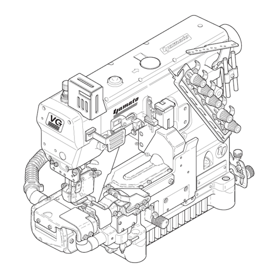
Page 9: Name Of Each Part
Adjusting screw (differential feed) Needle thread take-up guard Differential feed graduations Front cover Oil sight gauge Finger guard Main feed bar adjusting screw Hemming guide(right) Eye guard Screw (draining oil) Slide cover Suction pipe Fig. 1-1 VG3511-8F... -
Page 10: Installation
. Installation 2.1 Table cutting diagram 2.1.1 Table top type(Tyep A : standard) Fig. 2-1 VG3511-8F... - Page 11 2. Installation 2.1.2 Table top type (Type B ) Fig. 2-2 VG3511-8F...
-
Page 12: Table Top Type
2.2 Table top type Install a machine correctly referring to Figs. 2-3 and 2-4. sewing ⑤ machine sewing ⑤ machine ① ① ⑤ ② ⑤ ② ⑤ machine ② ③ table ② machine table ④ ④ ③ Fig. 2-3 Fig. 2-4 VG3511-8F... -
Page 13: Motor, Belt And Pulley
Or see Table 2 to select a proper motor pulley. 4200 4500 4700 Outside diameter Usual sewing speed × 64.5 + 5 mm 5000 of motor pulley Servomoter speed 5500 5500 Belt Table 2 Use a V-belt of M type. For belt size, refer to Table 1. VG3511-8F... -
Page 14: Hanging Belt
(2) Push the belt cover support ⑥ to the belt cover ⑤ to install it. (3) Fix the belt cover(lower) ⑦ on the machine table. (Fig. 2-9) Fig. 2-7 see from back side of machine ⑤ ⑥ ⑦ Fig. 2-9 Fig. 2-8 VG3511-8F... -
Page 15: Eye Guard And Finger Guard
2.7 Thread guide plate (1) Put the screws ③ into the hole of the thread ③ guide plate ④ and push it to the left. ④ (2) Fix the thread guide plate ④ with the screws ③ . Fig. 2-11 VG3511-8F... -
Page 16: Accessories
⑥. ⑦ ④ ⑤ ⑥ ③ ① ⑧ ② Fig. 2-12 A NOTICE If tightened the screw ③ excessively, the suction pipe(rear) ① may be deformed. That may be difficult to remove it when clogged with chips. VG3511-8F... -
Page 17: Sewing Speed And Rotating Direction Of Pulley
The rotating directions of the machine pulley ① and the handwheel ② are clockwise as shown in the figure. Fig. 3-1 If rotated in reverse direction, oil cannot be supplied properly. It can cause the damage to the machine. VG3511-8F... -
Page 18: Lubrication
. Lubrication Before lubricating, ALWAYS turn the power switch OFF and check that the machine has already stopped. 4.1 Lubricating oil Use YAMATO SF OIL No. 28. ① Never add additives to the oil. If added, it can cause the deterioration of the oil and the damage to the machine. -
Page 19: Changing Oil
④ ② NOTICE ③ Carefully check and replace them without spilling oil Fig. 4-7 stagnant in the oil filter ② when loosening screw ④ . VG3511-8F... -
Page 20: L U B R I C A T I N G O I
(Figs. 5-2 and 5-3) ② (4) Tighten the screws ① with a screwdriver. ① ATTENTION Tighten the screws ① with a tightening torque of 0.6N・m. Fig. 5-1 NO Fig. 5-2 Fig. 5-3 VG3511-8F... -
Page 21: Threading
After threading, push the lever ② (Thread D) to reset the thread take-up eyelet * For stretchless thread, thread directly to the looper ⑤ holder ① to the original position. through the looper thread release ③ . (Thread E) VG3511-8F... -
Page 22: P R E S S U R E O F P R E S S E R F O O
Adjust right-and-left position of the needle holes of the presser foot. Loosen the screw ④ . Move the front of the presser foot needles right or t so that the needle drops in the center of the needle drop. Then, tighten the screw ④ securely. Fig. 5-7 VG3511-8F... -
Page 23: A D J U S T I N G M O V E M E N T O F D I F F E R E N T I A L F E E D D O
● To increase the movement for gathering, turn it clock- Fig. 5-8 wise. ● To decrease the movement for stretching, turn it coun- terclockwise. (3) Tighten the lock nut ③ securely. gathering 【1:1.4】 ② uniform sewing 1:0.7 stretching ① Fig. 5-9 VG3511-8F... -
Page 24: A D J U S T I N G S T I T C H L E N G T
● To make the stitch length larger, turn it counterclock- ⑥ wise. Fig. 5-10 ③ number of stitch length stitch (per 1 inch) 1.4 ㎜ 18 stitches 2.0 ㎜ 13 stitches ④ 3.0 ㎜ 8.5 stitches 3.6 ㎜ 7 stitches ⑥ ⑤ Fig. 5-11 VG3511-8F... -
Page 25: Hemming Guide(Left) (
When sewing with the folder spacer ⑤ , the trimming width is 3.0 ㎜ . When sewing without it, the trimming width is 5.0 ㎜ . Remove the screw ④ to remove the folder spacer ⑤ . ① Fig. 5-13 VG3511-8F... -
Page 26: Hemming Guide(Right) (
(1) Loosen the screws ④ of the fabric guide(right) ③ . (2) Align the left end of the fabric guide(right) ③ with the guiding part of the hemming guide(right) ① . ④ ③ (3) Tighten the screws ④ securely. ① Fig. 5-15 VG3511-8F... - Page 27 Turn the adjusting screw ③ to adjust it. ③ ● To increase the pressure, turn it clockwise. ● To decrease the pressure, turn it counterclockwise. Fig. 5-17 VG3511-8F...
-
Page 28: Cleaning The Machine
NOTICE If the oil filter screen is clogged with dust, oil in the cyl- inder does not return to the oil reservoir. It can cause oil Fig. 5-20 leakage. VG3511-8F... -
Page 29: Adjustments
⑧ in the direction T. ⑧ ● To loosen the needle thread, move the SP device ⑧ in the direction L. (2) Tighten the screw ⑦ securely. Fig. 6-3 As standard, set the SP device at the highest point. VG3511-8F... - Page 30 ② with the top of the needle thread guide ③ , and make them parallel when the needle bar is at the low- est point. ③ Loosen the screw ④ to adjust the height and right-and- ④ left position of the needle thread guide ③ . ② Fig. 6-5 VG3511-8F...
-
Page 31: Top Cover Thread Tension
● To loosen the looper thread tension, lower both eyelets. ⑥ 3.0 ㎜ Fig. 6-7 ADVICE When using stretchable thread, move the thread take- up eyelets ④ and ⑤ to the lowest points. Do not thread through the top cover tension disc ⑥ . VG3511-8F... -
Page 32: Needle And Spreader
Adjust the height of the spreader so that the top cover thread passes behind the right needle and is caught by the left needle within adjustable range based on the nee- 8.5 - 9.5 ㎜ dle distance. stitch plate Fig. 6-9 ④ ③ Fig. 6-10 VG3511-8F... -
Page 33: Top Cover Thread Guide
(3) Set the eye of the top cover thread eyelet ⑤ along the extending line from the slot of the top cover thread ⑤ guide ① . (Fig. 6-12) ⑥ (4) Tighten the screw ⑥ securely. (Fig. 6-12) Fig. 6-12 VG3511-8F... -
Page 34: Distance Between Needle And Looper
A timing gauge has the marks (A, B, C, D, E) for each needle distance. Move the looper at the extreme right. Keep fitting the ① right needle into the groove “V” corresponding needle distance, and fit the looper tip to the gauge. Then, tighten the screw ② securely. Fig. 6-15 VG3511-8F... -
Page 35: Height Of Needle
⑤ and the looper tip to 0.2 - 0.3 ㎜ . Then, ⑤ tighten the screw ③ securely. ② ④ 2-needle ATTENTION 0.2 - ③ 0.3 ㎜ When tightening the screw ③ , back-and-forth position of the looper may be shifted. Recheck the position after ⑤ tightening it. Fig. 6-19 VG3511-8F... -
Page 36: Needle And Needle Guard(Rear)
(7) Check the clearance between the left needle and the needle guard(rear) ② is 0 - 0.05 ㎜ with keeping (6). (8) Tighten the screws ① and ④ securely. ① ④ Fig. 6-21 0 - 0.05 ㎜ 0 - 0.05 ㎜ Fig. 6-22 VG3511-8F... -
Page 37: Needle And Needle Guard(Front)
⑤ to 1.0 - 1.2 ㎜ when the feed dogs are at the highest points as standard. Also they are parallel to the top of the stitch plate. Loosen the screws ⑥ and ⑦ to adjust them. ⑦ ⑥ Fig. 6-26 VG3511-8F... -
Page 38: Changing Range Of Differential Ratio
Max. stitch length of the main feed dog is 2.3 ㎜ in a dif- ferential ratio of 1:2, and 3.0 ㎜ in 1:1.5 respectively. ① Fig. 6-27 1:2 gathering 1:1.5 1:1.1 Fig. 6-28 ③ ③ ② ④ ② Fig. 6-29 VG3511-8F... -
Page 39: Presser Foot Lift
⑥ and the collar ④ to 0.2 ㎜ when the presser foot is raised by 5.5 ㎜ (7.0 ㎜ ). (7) Tighten the screws ⑤ securely. ② ① Fig. 6-31 ⑥ ④ ⑤ 0.2 ㎜ spreader stitch plate 5.5 ㎜ Fig. 6-32 VG3511-8F... -
Page 40: Replacing Fabric Presser
① at ship- ment. Also packed for 25.4 ㎜ (one inch). Use the fabric ③ presser depending on hem width. To remove the fabric presser ② , loosen the screw ③ of the presser foot ① . ① ② Fig. 6-33 VG3511-8F... -
Page 41: Feeding Amount Of Puller (With Puller Mechanism)
● To increase the pressure for stretching, turn it clockwise. ● To decrease the pressure for gathering, turn it counterclockwise. Keep the pressure as to turn the spring ⑩ manually. (3) Tighten two screws ⑧ securely. ⑨ ⑩ ⑧ ⑦ Fig. 6-36 VG3511-8F... -
Page 42: Trimming Mechanism
⑤ of the collar(left) ⑥ . (6) Recheck the knifes cut properly. 7.0 ㎜ ④ ③ ATTENTION Refer to “7.2 Adjusting suction pipe(front)” and “7.3 Adjusting suction pipe cover” after changing trimming stitch plate position of a fabric. Fig. 7-2 VG3511-8F... -
Page 43: Adjusting Suction Pipe(Front)
(1) Loosen the screws ⑥ on the suction pipe cover ⑤ . (2) Align the right side of the suction pipe cover ⑤ with the inlet of the suction pipe(front) ② . (3) Tighten the screw ⑥ securely. ⑤ ⑥ Fig. 7-4 VG3511-8F... -
Page 44: Removing And Resetting Lower Knife
(4) Set the top of the lower knife ⑤ 7.0 ㎜ apart from the ④ upper knife ③ tip (at the base of the blade). Then, tighten the screw ② securely. (5) Recheck the knives cut properly. Fig. 7-6 7.0 ㎜ ⑤ ③ stitch plate Fig. 7-7 VG3511-8F... -
Page 45: Removing And Resetting Upper Knife
③ tip (at the base of the blade). Then, tighten the screw ② securely. (See Fig. 7-7) (7) Recheck the knives cut properly. Fig. 7-9 ⑤ 0.5 ㎜ ③ ⑨ stitch plate ⑩ 1.5 ㎜ ④ Fig. 7-10 Fig. 7-11 VG3511-8F... -
Page 46: Adjusting Upper Knife Stroke
(9) Recheck the knives cut properly. (10) Reset the bracket cover ② and the bracket cover gasket ③ with the screws ① . ⑧ ⑩ ⑪ ⑨ ④ ③ ② ⑥ ⑦ ⑤ ① Fig. 7-12 X ④ Y ⑤ Fig. 7-13 VG3511-8F... -
Page 47: Sharpening Knives
Re-sharpen the correct angle as in the figure. ADVICE Normal grinder is not useful to sharpen the upper knife ① made of super hard alloy. Contact us directly or the dealer for re-sharpening it. Fig. 7-14 10° 45° Fig. 7-15 VG3511-8F... -
Page 48: Specifications
Differential Feed Micro adjustment by adjuster Regulation Adjustable by moving external lever even during operation Lubrication Lubrication automatically by trochoid-shaped pump Lubricating Oil YAMATO SF OIL No.28 Capacity of 800 ml Oil Reservoir Installation Table top type Compliance with CE Marking... - Page 52 4-4-12, NISHI T ENM A , K I T A - K U , O S A K A , J A P A N T E L:81- 6 - 6 3 6 4 - 5 6 21 F A X:81- 6 - 6 3 6 5 - 718 5 〒530- 0047 ...
Need help?
Do you have a question about the VG3511-8F and is the answer not in the manual?
Questions and answers