Table of Contents
Advertisement
Instruction Manual
HIGH SPEED SMALL CYLINDER BED INTERLOCK STITCH MACHINE
VE2700-8 class
VE2711-1-8,VE2711-2-8F,VE2713-2-8F,VE2740PR-1-8F,VE2740PR-2-8F
Thank you for purchasing VE2700-8 class. Before using your VE2700-8 class, please read the
instruction manual and understand the contents well.
After reading the instruction manual, please keep it in a location where it is easily accessible
to the operator.
Advertisement
Table of Contents

Subscribe to Our Youtube Channel
Related Manuals for Yamato VE2700-8 class


Summary of Contents for Yamato VE2700-8 class
- Page 1 VE2700-8 class VE2711-1-8,VE2711-2-8F,VE2713-2-8F,VE2740PR-1-8F,VE2740PR-2-8F Thank you for purchasing VE2700-8 class. Before using your VE2700-8 class, please read the instruction manual and understand the contents well. After reading the instruction manual, please keep it in a location where it is easily accessible...
-
Page 2: Table Of Contents
CONTENTS Safety instructions ⅰ-ⅵ 1 . N a m e of e ach par t 2 . I n s tallat ion Table cutting diagram 2.1.1 Table top type (Type A: standard) 2.1.2 Table top type (Type B) 2.1.3 Semi-submerged type Installing the table top type Installing the semi-submerged type Pulley and belt... - Page 3 CONTENTS 5.12 Raising the upper feed roller (VE2740PR-8F) 5.13 Pressure of the upper feed roller (VE2740PR-8F) 5.14 SP device 5.15 Cleaning the machine 6. Ad jus t me n t s Needle thread tension Top cover thread tension Looper thread tension 6.3.1 Looper thread tension 6.3.2...
-
Page 4: Safety Instructions
SAFETY INSTRUCTIONS 1. Safety Instruction The sewing machine, automatic machine, and attachments (collectively called “the machine” below) involve sewing operations that require the operator to be near moving parts of the machine. Because of this, there is always a potential danger of unintentional contact with the moving parts. - Page 5 As dew condensation may occur when suddenly bringing death. Yamato assumes no responsibility for damages the machine from a cold environment to a warm place, or personal injury or death resulting from a machine in order to prevent accidents caused by breakage or which has been modified or altered.
- Page 6 SAFETY INSTRUCTIONS WARNING Disposal of the packaging 2.6 Items for which the power to the machine has to be turned off The packaging material of the machine consists of wood, paper, cardboard and polystyrene foam. The proper disposal Be sure to immediately turn the power off if any of the packaging is the responsibility of the customer, and abnormality or failure is found or in the case of power must be properly disposed of in accordance with the locally...
- Page 7 Use “Yamato SF oil 28” as specified. Securely join the table and legs to ensure sufficient If machine oil gets in your eyes, it may cause eye strength to withstand the weight of the sewing head inflammation.
- Page 8 SAFETY INSTRUCTIONS ○ Use genuine Yamato parts when repairing the machine WARNING and/or replacing the parts. We are not responsible for 3.5 During operation accidents caused by any improper repair/adjustment ○ Be sure to operate the sewing machine using the...
- Page 9 SAFETY INSTRUCTIONS 5. Safety devices and warning label affixing locations Belt cover, belt cover (small) Finger guard The belt cover prevents entanglement with the belt. The finger guard prevents the operator’ s fingers from going under the needle. However, there is some space at the top of Do not operate with the cover is removed.
- Page 10 Description : Industrial sewing machine Function : Make stitches and sew Applied harmonized standards in particular : EN ISO12100-1, EN ISO 12100-2, EN ISO10821, EN 60204-31 Manufacturer : YAMATO SEWING MACHINE MFG. CO., LTD. 2-10-3 Hotarugaike Minami-machi Toyonaka Osaka Japan...
-
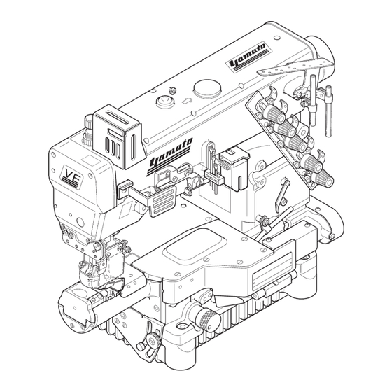
Page 11: Name Of Each Part
Name of each part Thread guide plate Top cover seal plug (for oiling) Handwheel SP device Oil sight window Needle thread take-up Needle bar guard Presser spring regulator Thread tension spring cap Belt cover (small) Needle thread take-up guard Finger guard Presser foot Front cover Side cover... -
Page 12: Installation
Installation 2.1 Table cutting diagram 2.1.1 Table top type (Type A: standard) The circled dimensions are required only for models with UT device. Fig. 2-1 VE2700-8... - Page 13 2. Installation 2.1.2 Table top type (Type B) The circled dimensions are required only for models with UT device. Fig. 2-2 VE2700-8...
-
Page 14: Semi-Submerged Type
2. Installation 2.1.3 Semi-submerged type Fig. 2-3 VE2700-8... -
Page 15: Installing The Table Top Type
2. Installation 2.2 Installing the table top type Install the machine correctly referring to Figs. 2-4, 2-5. Sewing machine ⑤ ⑤ Sewing machine ① ① ② ⑤ ⑤ ② ⑤ ② Machine ② ③ ④ table Machine table ③ ④ Fig. -
Page 16: Pulley And Belt
2. Installation 2.4 Pulley and belt Proper sizes of the pulley and the belt differ according to the table type and the sewing speed. To install the motor, see the instruction manual for the 61 ㎜ motor. 40° Servomotor 5.5 ㎜ Use a servomotor with an output of 500 W or more. -
Page 17: Hanging The Belt
2. Installation 2.5 Hanging the belt ② ① Before performing this work, ALWAYS turn the power switch OFF and check that the motor has already stopped. 10-20 ㎜ Use a V-belt of M-type. ③ (1) Hang the belt ① on the machine pulley ②, and then Push 10N on the motor pulley ③... -
Page 18: Eye Guard And Finger Guard
2. Installation 2.7 Eye guard and finger guard To ensure safe use, always install the eye guard ① and the finger guard ② in position during operation. ① ② Fig. 2-12 2.8 Thread guide plate (1) Loosen the screws ③. ③... -
Page 19: Sewing Speed And Rotating Direction Of The Pulley
Sewing speed and rotating direction of the pulley The maximum sewing speed is 4500 sti/min (during inter- mittent operation). ② Run a new machine at speed about 15 to 20 % lower than the maximum sewing speed for the first 200 hours (for about one month) so that the machine can offer a long service life in good condition. -
Page 20: Lubrication
Before performing this work, ALWAYS turn the power switch OFF and check that the motor has already stopped. 4.1 Lubricating oil Use YAMATO SF OIL 28. Never add additives to oil. If added, it can cause deterioration of oil and dam- ①... -
Page 21: Changing Oil
4. Lubrication 4.3 Changing oil Period of changing oil When using a new machine, change lubricating oil after running a machine for 200 hours (for about one month). After that, change oil once or twice a year. Procedure for changing oil (1) Remove the belt cover. -
Page 22: Proper Operation
Proper operation 5.1 Needle system Use UY×128GAS (UY128GAS). Japanese standard Select a proper needle in size depending on the thickness Metric standard and type of material. Table 3 5.2 Installing the needles Before performing this work, ALWAYS turn the power switch OFF and check that the motor has already stopped. -
Page 23: Threading
5. Proper operation 5.3 Threading Without UT, UT-A device When not threaded, thread correctly as shown in Fig. 5-4. Before performing this work, ALWAYS When had been threaded, knot the preset thread and new turn the power switch OFF and check one together to rethread. - Page 24 5. Proper operation With UT, UT-A device When not threaded, thread correctly as shown in Fig. 5-5. For stretchable thread When had been threaded, knot the preset thread and new with UT, UT-A device one together to rethread. A, B, C: Needle thread Pull out the threads until they come to the front of the needles.
-
Page 25: Adjusting The Thread Tension
5. Proper operation 5.4 Adjusting the thread tension Adjust the thread tension with the thread tension spring caps ① depending on material type, thread type, seam width, stitch length, and other sewing conditions. ● To tighten the thread tension, turn the caps clockwise. ●... -
Page 26: Adjusting The Movement Of The Differential Feed Dog
5. Proper operation 5.7 Adjusting the movement of the differential feed dog Before performing this work, ALWAYS turn the power switch OFF and check that the motor has already stopped. Loosen the screw ①. For gathering sewing, move the screw ① upward. Gathering (Maximum normal differential ratio 1:1.4) For stretching sewing, move the screw ①... -
Page 27: Adjusting The Stitch Length
5. Proper operation 5.8 Adjusting the stitch length Before performing this work, ALWAYS turn the power switch OFF and check that the motor has already stopped. Stitch length is adjustable from 1.4 to 4.2 mm. Stitch length Number of stitch Number of stitch Table 4 shows the number of stitches per inch (25.4 mm) ( ㎜... -
Page 28: Adjusting The Fabric Guide (Ve2713-8F)
5. Proper operation 5.9 Adjusting the fabric guide (VE2713-8F) For tip over covering seam Seam (1) Loosen the screws ① of the fabric guide. (2) Insert the seam between the fabric guide (right) ② and the fabric guide (left) ③. (3) Locate the seam at the center of the right needle and ②... -
Page 29: Pressure Of The Walking Presser Foot (Ve2711-8F-Wf1)
5. Proper operation 5.10 Pressure of the walking presser foot (VE2711-8F-WF1) The walking presser foot can prevent ply shift between upper and lower materials in hemming operation. It also ② can feed materials smoothly even if running at high speed of 4500 sti/min or over. -
Page 30: Raising The Upper Feed Roller (Ve2740Pr-8F)
5. Proper operation 5.12 Raising the upper feed roller (VE2740PR-8F) To pull out a jamming material, raise the upper feed roller ① by raising the upper feed roller lifting lever ②. The upper feed roller ① can be kept at the raised oisition by moving the upper feed roller lifting lever ②... -
Page 31: Sp Device
5. Proper operation 5.14 SP device Use the SP device (for needle thread oiling) equipped as standard to prevent thread breakage, skip stitch and larg- ① er needle hole on material when running a machine at high speed or using synthetic thread and/or synthetic material. Use dimethyl silicon oil. -
Page 32: Cleaning The Machine
5. Proper operation 5.15 Cleaning the machine Before performing this work, ALWAYS turn the motor switch OFF and check that the motor has already stopped. ① The sewing machine should be cleaned at the end of every working day. Grooves of the stitch plate and the area around the feed dogs, the looper thread take-up and the oil filter screen should be cleaned once a week. -
Page 33: Adjustments
Adjustments Before performing this work, ALWAYS turn the power switch OFF and check that the motor has already stopped. 6.1 Needle thread tension 34.5 ㎜ Needle thread take-up How to adjust (1) Loosen the screws ②③. ① ● To tighten the needle thread tension, move the nee- dle thread take-up ①... -
Page 34: Top Cover Thread Tension
6. Adjustments Some kinds of thread may cause skip stitch because a loop cannot be formed well and the looper fails to catch the needle thread. In this case, thread the needle thread through the needle ① thread retainer disc ② of the needle thread retainer sup- port (No. -
Page 35: Looper Thread Tension
6. Adjustments ① 6.3 Looper thread tension ③ 6.3.1 Looper thread tension ② As standard, align the eyes of the thread take-up eyelets Decrease Decrease ③④ with the mark ② of the cast-off plate ①. Loosen the screws ⑤ and adjust the looper thread tension Increase Increase by moving the thread take-up eyelets ③④. -
Page 36: Relation Between The Needle And The Spreader
④ ③ Fig. 6-12 ① ① 8.5-9.5 ㎜ 8.0-9.0 ㎜ Stitch plate Stitch plate Fig. 6-13 VE2700-8 class Fig. 6-14 VE2711-1-8 (except for VE2711-1-8) VE2700-8... -
Page 37: Top Cover Thread Guide
6. Adjustments 6.4.2 Top cover thread guide (1) Loosen the screws ② of the top cover thread guide ①. ② (Fig. 6-15) ⑤ (2) Adjust the clearance between the top surface of the ① spreader ③ and the bottom of the top cover thread guide ①... -
Page 38: Distance Between The Needle And The Looper
6. Adjustments 6.5 Distance between the needle and the looper The distance between the looper tip and the center of the right needle differs according to the needle distance when the needles are at the lowest points and the looper ①... -
Page 39: Height Of The Needle
6. Adjustments 6.7 Height of the needle (1) Install the needle into the left hole of the needle clamp. (2) Make sure the looper has been inserted into the looper holder fully. (3) When the looper moves to the left from the right, turn the handwheel until the looper tip meets the center of the left needle. -
Page 40: Needle And Needle Guard
② of the needle guard (rear) ① with the bottom of the needle eye of the right needle ③. (Fig. 6-25) ① ② Fig. 6-24 VE2700-8 class (except for VE2711-1-8) ③ ① Back-and-forth position of the needle guard (rear) (1) Loosen the screws ④⑤. -
Page 41: Needle Guard (Front)
6. Adjustments 6.9.2 Needle guard (front) (1) Loosen the screws ②③. (Fig. 6-29) (2) Turn the handwheel clockwise until the looper tip comes to the center of the left needle. Adjust the height of the needle guard (front) ① so that the corner ①... -
Page 42: Height Of The Feed Dog
6. Adjustments 6.10 Height of the feed dog When the feed dogs are at the highest points, the tops of the feed dogs and the top of the stitch plate are parallel. (1) Loosen the screws ③④. ② ① 1.0-1.2 ㎜ (2) When the feed dogs are at the highest points, adjust the differential feed dog ①... -
Page 43: Removing The Presser Foot And Presser Foot Lift
6. Adjustments 6.11 Removing the presser foot and presser foot lift The presser foot lift for the needle distance of 5.6 mm is ① as follows: - with spreader: 5.0 mm ⑨ - without spreader: 7.0 mm Removing the presser foot (1) Loosen the screws ②... -
Page 44: Toeing Up And Down The Presser Foot
6. Adjustments 6.12 Toeing up and down the presser foot ○ Toeing up and down the presser foot (Standard) A: Standard The presser foot can be toed up and down between 0° and 5° . (Fig. 6-37A) ○ Toeing up the presser foot Loosen the screw ①. -
Page 45: Adjusting The Walking Presser Foot (Ve2711-8F-Wf1)
6. Adjustments 6.13 Adjusting the walking presser foot (VE2711-8F-WF1) Correct balance between the presser bar spring ① and the walking presser foot spring ② is required for the walking presser foot to operate properly. ⑬ ⑧ (1) Adjust the height of the walking presser foot spring ②... -
Page 46: Feeding Amount Of The Puller (Ve2740Pr-8F)
6. Adjustments 6.14 Feeding amount of the puller (VE2740PR-8F) (1) Remove the top cover seal plug ①. (2) Turn the handwheel until the screw ② of the upper feed roller regulator comes to the right above. ① Loosen the screw ② with a hexagon socket screw- driver. -
Page 47: Specifications
Lever type (adjustable with a screwdriver) Regulation Lubrication Automatic lubrication by trochoid-shaped pump (in combination with splash lubrication) Lubricating Oil YAMATO SF OIL 28 Capacity of 800 ml Oil Reservoir Installation Table top type or semi-submerged type (exclusive supporting board is necessary) - Page 48 4 - 4 - 12, NISHITENMA, KITA-KU, OSAKA, JAPAN 530-0047 TEL:81-6-6364-5621 FAX:81-6-6364-7185 〒530-0047 大阪市北区西天満 4 丁目 4 番12 号 TEL(06)6364-562 1 (代) FAX(06)6364-7 1 85 P/N 9720450 ( I ) No.1 Edited in 2021.11 Printed in Japan 2021.1 1 (VE2700-8)
Need help?
Do you have a question about the VE2700-8 class and is the answer not in the manual?
Questions and answers