Table of Contents
Advertisement
VT1500.2500_01
Instruction Manual
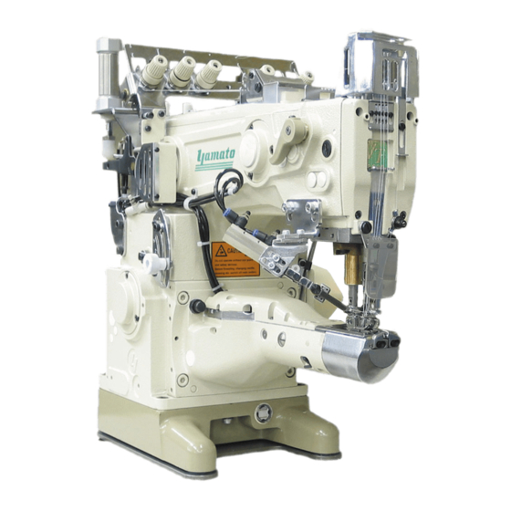
3-Needle Cylinder Bed
Interlock Stitch Machine
VT2500
Class
Thank you for purchasing this product. This instruction manual contains infor-
mation on how to handle this product and precautions in usage. Before using
the product, read this instruction manual carefully and familiarize yourself with
its content. Also, keep this manual in safe handy place so that others may use
it as future reference.
Advertisement
Table of Contents

Related Manuals for Yamato VT2500


Summary of Contents for Yamato VT2500
-
Page 1: Instruction Manual
VT1500.2500_01 Instruction Manual 3-Needle Cylinder Bed Interlock Stitch Machine VT2500 Class Thank you for purchasing this product. This instruction manual contains infor- mation on how to handle this product and precautions in usage. Before using the product, read this instruction manual carefully and familiarize yourself with its content. -
Page 2: Table Of Contents
Contents Safety Instructions i ~ iv 1. Name of each part 2. Installation 2.1 Table top type ..............................2 2. 1 . 1 Table cutting diagram ..............................2 2. 1 .2 Installation onto table ..............................3 2.2 Semi-submerged type ..........................4 2.2. 1 Table cutting diagram ..............................4 2.2.2 Installation onto table . - Page 3 This product is subject to change without notice. Due to such event, the contents of this manual may not match the product in some regards. Every effort has gone into making this manual, nevertheless should you discover any mistakes or missing information, please note that it may not always be possible for Yamato to correct those errors immediately.
-
Page 4: Safety Instructions
Safety Instructions 1.4 Unpacking and transportation 1. To ensure safe use (1) Unpack from the top. Always observe the following instructions to (2) Never hold the parts near the needle or ensure the safe use of the industrial sewing threading parts when removing the sewing machines and devices. - Page 5 (1) F o l l o w t h e i n s t r u c t i o n m a n u a l s f o r before operating the sewing machine. maintenance, inspection, and repair. Use the Yamato SF oil as specified. (2) Entrust the maintenance, inspection, and (3) Never put your hand under the needle or repair to specially trained personnel.
- Page 6 Safety Instructions 4. Caution signs and alert pictorial markings 5. Warning labels on sewing machines This label indicates that This instruction manual contains the following removal of the safeguards caution signs and alert pictorial markings a n d w o r k s e x c e p t f o r to prevent you from injuring yourself or the sewing performance while sewing machine from being damaged.
- Page 7 Safety Instructions 6. Location of Safety Labels Safety labels are placed adjacent to potential hazards. Keep these labels clean and easily readable at all times; should a label become damaged or lost, a replacement should be ordered. VT1500.2500_01...
-
Page 8: Name Of Each Part
1. Name of each part ●Lifter lever ●Presser spring regulator VT1500.2500_01 ●Presser foot release lever ●Presser foot ●Oil sight window ● Thread tension ●Finger guard unit ●Chain cutter ●Pushbutton ●Differential lever ●Eye guard ●Cylinder front cover ●Pulley ●Oil reservoir ●Oil gauge VT2500... -
Page 9: Installation
2. Installation 2.1 Table top type 2.1.1 Table cutting diagram VT2500... -
Page 10: Installation Onto Table
Fig. 004, 005 and 006. (1) Attach the bolts and nuts to the machine table. (2) Cover the bolts with the rubber cushions. Machine table (3) Set the sewing machine over the rubber cushions. Sewing machine Rubber Machine table cushion VT2500... -
Page 11: Semi-Submerged Type
2. Installation 2.2 Semi-submerged type 2.2.1 Table cutting diagram VT2500... -
Page 12: Installation Onto Table
④ or adjust the ④ number of the supporting board spacers ⑤. ② ● The top surface of the stitch plate is typically ⑤ approx. 100 mm high from the table. Machine table Machine ① ③ ⑤ ④ Supporting board VT2500... -
Page 13: Motor, Pulley And Belt
◇ Numerical figures are examples for servomotors diameters with every 5 mm increment, therefore of 3000 and 3600 rpm. select a pulley of an outer diameter that is near to the calculated outer diameter. Belt Use an M-type V-belt. For sizes, see Table 1. VT2500... -
Page 14: Hanging Belt
SUPPLEMENT Semi-submerged installation of the machine requires the supplementary belt cover to be installed before the machine is mounted on the table and the belt is hanged in place. See page 8. VT2500... -
Page 15: Belt Cover Installation
③ (3) Attach the belt cover(lower) ④ to the sewing machine with the screws ⑤. ⑤ ④ (4) Fit the belt cover(upper) ⑥ onto the belt ⑥ cover(lower) ④ and lock in place with the screws ⑦. ⑦ ④ VT2500... -
Page 16: Thread Tension Unit Installation
⑦ ⑥ 2.7 Eye guard and finger guard installation CAUTION Use the sewing machine with the eye guard ⑧ and the finger guard ⑨ attached. Also, lower the eye guard ⑧ to the set position when working. ⑧ ⑨ VT2500... -
Page 17: Presser Lifter Pedal Installation
When attaching pedal to the left side of table ⑦ ⑦ ⑧ ⑧ ④ ② ③ ① ② ⑤ ② ② ④ ⑥ ① ① ① ⑧ ⑤ ③ ⑥ To presser lifter pedal ⑧ To presser lifter pedal VT2500... -
Page 18: Supplementary Cover Installation
⑦ and the washers ⑧. ② ③ CAUTION ① Turn off the power switch of the motor and check the motor has stopped before installing the supplementary cover. Working with the power on can result in injury. ⑦ ④ ⑧ ① ⑥ ⑤ VT2500... -
Page 19: Sewing Speed And Pulley Rotating Direction
◇ Both the motor pulley ② and the machine pulley ① rotate in the clockwise direction. CAUTION ② If the pulleys rotate in reverse direction, oil can not be properly supplied to parts resulting in sewing machine breakdown. VT2500... -
Page 20: Lubrication
① Do not use oil additives as they can deteriorate the oil resulting in sewing machine breakdown. ◇ Lubricating oil: YAMATO SF OIL No.28 ◇ Capacity of oil reservoir: 600 mL 4.2 Lubricating When using a sewing machine for the first time A sewing machine is shipped with the oil drained. -
Page 21: Changing Oil
(7) Remove the seal plug ② labeled "OIL". (8) Change with new oil. (See page 13.) (9) Set the sewing machine on the machine table. (10) Hang the V-belt around the motor pulley and reinstall the belt cover. (See page 7 and 8.) VT2500... -
Page 22: Oil Filter Check And Replacement
◇ If the oil filter ① is broken, replace with a new filter. CAUTION ● When removing the oil filter cap ② , oil in the oil filter ① may spill out. ● Insert the oil filter ① into the inmost to install it properly. VT2500... -
Page 23: Proper Operation
● Use 0.6 N ・m (6 kgf ・cm) of torque to tighten the screws ③. ② ● After replacing a needle, check the distance between the needle and looper, and between the needle and needle guards (See pages 27 and 29). VT2500... -
Page 24: Threading
038. ① SUPPLEMENT Pulling the thread take-up eyelet holder ① to the front makes it easier to thread the looper thread. Once threaded, press on the thread take-up eyelet holder until hearing it catch in its original position. VT2500... -
Page 25: Thread Tension Unit Adjustment
S 1:0.8 Stretching of 4 mm is available up to 1:1.5 ● At the maximum differential ratio of 1:2, the stitch 1:1.5 Stitch length: 4mm or less length is 3 mm or less. Stitch length: 3mm or less VT2500... -
Page 26: Stitch Length Adjustment
● To make the stitch length smaller, turn the pulley counterclockwise. (4) Once the marks are aligned, release the ③ pushbutton ①. CAUTION Check that the pushbutton ① has returned to it's original position and that the machine pulley ③ rotates smoothly. VT2500... -
Page 27: Sp Device
● To unlock and lower the presser foot, raise up the presser foot release lever ④ fully. SUPPLEMENT Turning the presser foot release lever ④ while toeing down the presser lifter pedal makes it easier to move the presser foot. VT2500... -
Page 28: Fabric Edge Guides Adjustment
⑩ ⑨ ⑪ and adjust the clearance between the fabric guide(right) ⑨ and fabric guide(left) ⑩ to feed the fabric smoothly. Seam Fabric (3) Once the clearance has been adjusted, tighten the screws ⑪. VT2500... -
Page 29: Cleaning
◇ Once a week, remove the cylinder front cover and the presser foot to clean the grooves in the stitch plate and the feed dog area. VT2500... -
Page 30: Machine Adjustment
Loosen the screws ⑨ ⑩ to adjust the holder⑧ . Once the holder has been positioned, tighten the screws ⑨ ⑩. ● To make loop smaller, lower the holder. ● To make loop larger, raise the holder. VT2500... -
Page 31: Top Cover Thread Tension Adjustment
When the needle bar is at the highest point (top dead center), adjust the looper thread take-up ⑤ to the position where the looper starts taking up the thread. To adjust the position, loosen the ⑤ set screw ⑥ of the looper thread take-up ⑤ VT2500... -
Page 32: Needle And Spreader Adjustment
Match the height of the spreader ① according to the needle distance within the adjustment range, so that the top cover thread can pass behind the right needle and be caught by the left needle. ① 11 - 12mm Stitch plate VT2500... -
Page 33: Top Cover Thread Guide Adjustment
(See Fig. 060.) (2) Align the hole of the top cover thread eyelet ⑤ to the extension from the slot on the top cover thread guide ①. (See Fig. 061.) (4) Tighten the screw ⑥. (See Fig. 061.) VT2500... -
Page 34: Needle And Looper Adjustment
When using 2-needle ● When tightening the screw ③ , the looper ① may move in the front-and-rear position. After tightening 0.2mm - 0.3mm the screw ③, recheck the front-and-rear position of ⑦ the looper ①. VT2500... -
Page 35: Needle Height
11.0(11.0 - 11.2)mm (5) Retighten the screw ①. 5.6 ㎜ 11.0(10.9 - 11.1)mm CAUTION 6.4 ㎜ 11.0(10.8 - 11.0)mm Before retightening the screw ①, wipe the old gasket clean and coat with liquid gasket. Dirt can cause oil leakage. ② ① VT2500... -
Page 36: Needle Guard(Rear) Adjustment
(1) Loosen the screw ⑤ and position the needle guard(front) ④ so that the clearance between it and each needle is 0 - 0.3 mm when the ④ looper tip comes to the center of the left ⑤ needle. (2) Tighten the screw ⑤. 0mm - 0.3mm VT2500... -
Page 37: Feed Dog Height Adjustment
⑪ . Loosen the screw ⑫ on the presser foot ⑧ and turn the presser foot ⑧ to the left and right until the needles ⑩ drop in the center of ⑩ the needle hole ⑪ on the presser foot ⑧. ⑧ ⑪ VT2500... -
Page 38: Presser Foot Stopper Collar Adjustment
(1) Press the lifter lever ⑥ downward, and insert the presser foot ⑤ into the presser bar ⑦. ⑥ (2) Position the presser foot ② as explained in "6.10 Presser Foot Position Adjustment" (page 30), and tighten the screw ④. VT2500... -
Page 39: Toubleshooting
O i l d o e s n o t Is oil level below the line on the oil Add oil. 13・14 come from nozzle gauge? Is the oil filter clogged? Replace the oil filter. VT2500... -
Page 40: Specifications
Differential ratio Max. normal differential 1:2, Max. reverse differential 1:0.8 Differential feed regulation External lever Lubrication Automatic lubrication by trochoid-shaped pump Lubricating oil YAMATO SF OIL No.28 Capacity of oil reservoir 600mL Installation "Table top installation" or "Semi-submerged installation" VT2500... - Page 41 〒530- 0047 大 阪 市 北 区 西 天 満 4 丁 目 4 番 1 2 号 TEL( 0 6 ) 6 3 6 4-13 21 ( 代 ) FAX( 0 6 ) 6 3 6 5- 517 6 P/N 9720256 (I) No.2 Edited in 2008.5 Printed in Japan 2008.5.1H Y (VT2500)...
Need help?
Do you have a question about the VT2500 and is the answer not in the manual?
Questions and answers