
Subscribe to Our Youtube Channel
Related Manuals for Condair HP


Summary of Contents for Condair HP
- Page 1 READ AND SAVE THESE INSTRUCTIONS INSTALLATION AND OPERATION MANUAL Adiabatic humidification system Condair HP/HPRO Valid from 2021 Humidification and Evaporative Cooling...
- Page 2 Condair A/S, except to the extent required for installation or maintenance of recipient's equipment. Liability Notice Condair A/S does not accept any liability due to incorrect installation or operation of the equipment or due to the use of parts/components/equipment that are not authorized by Condair A/S.
-
Page 3: Table Of Contents
Compound system Condair HP (master-slave configuration) 3.2.3 Overview pump station Condair HP 3.2.4 Flow diagram pump station Condair HP 100 - 800 3.2.5 Part specification pump station Condair HP 100 - 800 3.2.6 Flow diagram pump station Condair HP 1300 3.2.7... - Page 4 How to connect to power supply Initial commissioning Cabinet layout Insert inlet filter Insert RO membrane (only for Condair HPRO models) Mount sterile breathing filter (only for Condair HPRO models) Set up the controller Flushing procedure 6.6.1 Flushing the HPRO pump unit and RO membrane 6.6.2...
- Page 5 Operation Daily operation Weekly inspection Taking the HP/HPRO out of operation Dismantling and disposal Maintenance Important notes on maintenance Maintenance work Part list for preventive maintenance Maintenance indications Disassembling and assembling of the mist eliminator for cleaning Troubleshooting 10.1 Important notes on troubleshooting 10.2...
-
Page 6: Introduction
(“Condair HP” for short). The Condair HP incorporates the latest technical ad van ces and meets all recognized safety stand- ards. Nevertheless, improper use of the Condair HP may result in danger to the user or third parties and/or impairment of material assets. -
Page 7: Symbols Used In This Manual
If the equipment changes hands, the documentation must be passed on to the new operator. If the documentation gets misplaced, please contact your Condair representative. 1.2.3 Language versions This installation and operation manual is available in various languages. Please contact your Condair representative for information. Introduction... -
Page 8: Health And Safety
The Condair HP is intended exclusively for humidification in ventilation systems within the speci- fied operating conditions. Any other type of application without the express written consent of the manufacturer is considered as not conforming with the intended purpose and may lead to the Condair HP becoming dangerous. -
Page 9: Danger That May Arise From The Condair Hp
– after long-time storage under unfavourable conditions. – after transportation under unfavourable conditions. All persons working with the Condair HP must report any alterations to the unit that may affect its safety to the owner without delay. Health and Safety... -
Page 10: Prohibited Modifications To The Unit
Prohibited modifications to the unit No modifications may be undertaken on the Condair HP without the express written consent of the manufacturer. For the replacement of defective components use exclusively original accessories and spare parts available from your Condair representative. - Page 11 30 minutes, and disinfect the system if this proves to be necessary. Condair follows the guidelines in VDI 6022 for CFU counts in humidifiers. The CFU count in the hu- midification water must hence not exceed 200 CFU/ml, corresponding to a maximum BQ value of 57.
-
Page 12: Disinfection
Disinfection We recommend Sanosil as a disinfection agent in HP Systems. Disinfection should be carried out at least once a year, depending on the inlet water quality. Calculation of mixing ratio between water and chemical - 5 % Sanosil S010 Ag to 0.1 % Wanted concentration: 0.1 %... -
Page 13: Overview Of Condair Hp And Hpro
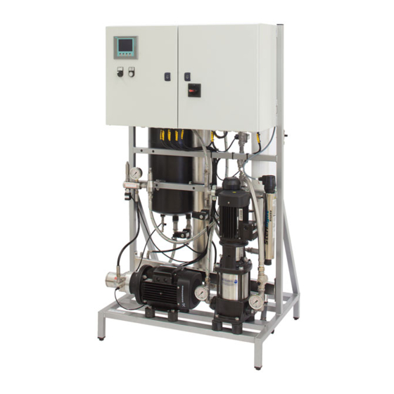
Nozzle unit Droplet separator (option) Flushing valve MV5 high-pressure system Pump station consisting of: High-pressure pump Control unit, with touch screen High-pressure flexible hose UV-light system (option) Fig. 1: Stand-alone system Condair HP (master configuration) Overview of Condair HP and HPRO... -
Page 14: Compound System Condair Hp (Master-Slave Configuration)
Compound system Condair HP (master-slave configuration) Assuming the system data is within a defined range, the pump station of a stand-alone system may supply pressurized water to up to three further HP systems (slave systems). A so-called master-slave configuration is shown below. -
Page 15: Overview Pump Station Condair Hp
3.2.3 Overview pump station Condair HP Fig. 3: Overview pump station Condair HP Overview of Condair HP and HPRO... -
Page 16: Flow Diagram Pump Station Condair Hp
3.2.4 Flow diagram pump station Condair HP 100 - 800 Fig. 4: Flow diagram pump stations Condair HP 100 - 800 3.2.5 Part specification pump station Condair HP 100 - 800 Inlet filter 20", 1µm Frequency drive VFD Pressure gauge 0-16 bar... -
Page 17: Flow Diagram Pump Station Condair Hp 1300
3.2.6 Flow diagram pump station Condair HP 1300 Fig. 5: Flow diagram pump station Condair HP 1300 3.2.7 Part specification pump station Condair HP 1300 Inlet filter 20", 1µm Frequency drive VFD Pressure gauge 0-16 bar Pressure gauge 0-16 bar... -
Page 18: Brief Description Of High-Pressure Pump Station
The pump station is electrically wired at the factory. At the installation site, main power supply, the humid- ity signal or humidity sensor, external safety chain, step valves and chosen options must be electrically connected to the control unit. Overview of Condair HP and HPRO... -
Page 19: Condair Hpro System Overview
Control unit, with touch screen High-pressure flexible hose RO water treatment system (option) a: RO pump b: RO Membrane c: RO water storage tank UV-light system 10 Water meter Fig. 6: Stand-alone system Condair HPRO (master configuration) Overview of Condair HP and HPRO... -
Page 20: Compound System Condair Hpro (Master-Slave Configuration)
Pump station is controlled by the pump station and addition 3 Slaves, if needed, or it can consist of a pump station and up to 4 Slaves. Fig. 7: Compound system Condair HPRO (master-slave configuration) Overview of Condair HP and HPRO... -
Page 21: Overview Pump Station Condair Hpro
Overview pump station Condair HPRO 100, 200, 300 Fig. 8: Overview pump station Condair HPRO 100, 200, 300 3.3.4 Flow diagram pump station Condair HPRO 100, 200, 300 Fig. 9: Flow diagram pump station Condair HPRO 100, 200, 300 Overview of Condair HP and HPRO... -
Page 22: Part Specification Pump Station Condair Hpro
3.3.5 Part specification pump station Condair HPRO 100, 200, 300 Permeate container, 55 l Drain pipe Inlet filter 20", 5 µm Sterile breathing filter 0.2 µm Suction filter Frequency drive VFD Pressure gauge 0-16 bar Pressure gauge 0-16 bar Pressure gauge 0-160 bar... -
Page 23: Overview Pump Station Condair Hpro 500
3.3.6 Overview pump station Condair HPRO 500 US F2 P1/M1 Fig. 10: Overview pump station Condair HPRO 500 Overview of Condair HP and HPRO... -
Page 24: Flow Diagram Pump Station Condair Hpro 500
3.3.7 Flow diagram pump station Condair HPRO 500 Fig. 11: Flow diagram pump station Condair HPRO 500 3.3.8 Part specification pump station Condair HPRO 500 Permeate container, 55 l Drain pipe Inlet filter 20", 5 µm Sterile breathing filter 0.2 µm... -
Page 25: Overview Pump Station Condair Hpro 800
3.3.9 Overview pump station Condair HPRO 800 M1/P1 RO 1-3 Fig. 12: Overview pump station Condair HPRO 800 Overview of Condair HP and HPRO... -
Page 26: Flow Diagram Pump Station Condair Hpro
3.3.10 Flow diagram pump station Condair HPRO 800 Fig. 13: Flow diagram pump station Condair HPRO 800 3.3.11 Part specification pump station Condair HPRO 800 Permeate container, 55 l Drain pipe Inlet filter 20", 5 µm Sterile breathing filter 0.2 µm... -
Page 27: 3.3.12 Brief Description Of Pump Station
The pump station is electrically wired at the factory. At the installation site, main power supply, the humid- ity signal or humidity sensor, external safety chain, step valves and chosen options must be electrically connected to the control unit. Overview of Condair HP and HPRO... -
Page 28: Humidifier Unit
13 Siphon (by customers, height adapted to duct pressure) 14 Separation element humidifier unit (min. height: 3 cm, sealed towards the duct floor and the duct walls) 15 Drain hose from flush valve MV5 Fig. 14: Humidifier Unit Overview of Condair HP and HPRO... -
Page 29: Nozzle Unit
The installation of a droplet separator is the customer’s responsibility. An optional Condair droplet sepa- rator is available for the Condair HP. Note regarding the Condair droplet separator: Due to the special surface finish of the separator profiles the Condair droplet separator unfolds its full effect not before 4-8 weeks after the initial commissioning (time depending on the water quality on site). -
Page 30: Control
Reg valves which gives a 15-stage regulation (option). 3.5.4 Monitoring of high-pressure pump The supply pressure and pump temperature are permanently monitored. The HP pump automatically stops if one of these values is outside the admissible range. A respective error message appears in the display. -
Page 31: Notes On Planning
Important notes: – If a particular site is to be equipped with several HP systems, determine the above data for each system separately. Your Condair representative will then evaluate whether the particular systems may be operated in a master-slave compound configuration. -
Page 32: Options And Accessories
The pump station is fitted with four digital status relays: Alarm (pump stopped), On/off status, Humidifying and Maintenance Communication Gateway Communication gateway using the TCP/IP protocol, integrating the Condair HP/HPRO into a monitoring, automation or BAS system. Integrated RO-system Provides a high performance reverse osmosis water treatment system integrated directly into the high-pressure pump skid. -
Page 33: Installation Works
(electrician or workman with equivalent training). Safety For all installation work the ventilation system in which the Condair HP will be installed is to be rendered inoperative and prevented from further inadvertent operation. The pump station and possible Slave control units may be connected to electric mains only after all installation work has been completed. -
Page 34: System Set-Up
Control humidity signal, 0... 10 V or 4...20 mA control/humidity signal Internal communication, RJ45 cable, LAN, TCP/IP protocol Water supply (HP: 1 .. 4 bar, HPRO: 2.5 ... 7 bar) High pressure water to valve block and nozzle lines, 60 ... 70 bar Fig. -
Page 35: Compound System (Master-Slave Configuration 1 Or 2 Slaves)
Control humidity signal, 0... 10 V or 4...20 mA control/humidity signal Internal communication, RJ45 cable, LAN, TCP/IP protocol Water supply (HP: 1 .. 4 bar, HPRO: 2.5 ... 7 bar) High pressure water to valve block and nozzle lines, 60 ... 70 bar Fig. -
Page 36: Compound System (Master-Slave Configuration 3 Slaves)
Water supply (HP: 1 .. 4 bar, HPRO: 2.5 ... 7 bar) High pressure water to valve block and nozzle lines, 60 ... 70 bar Fig. 17: Compound system (master-slave configuration 3 slaves) Note: The data switch used when connecting 3-4 slaves are not supplied by Condair Installation works... -
Page 37: Compound System (Slave Configuration 4 Slaves)
Water supply (HP: 1 .. 4 bar, HPRO: 2.5 ... 7 bar) High pressure water to valve block and nozzle lines, 60 ... 70 bar Fig. 18: Compound system (slave configuration 4 slaves) Note: The data switch used when connecting 3-4 slaves are not supplied by Condair Installation works... -
Page 38: Compound System >800 L/H (Master-Slave Configuration 3 Slaves)
Water supply (HP: 1 .. 4 bar, HPRO: 2.5 ... 7 bar) High pressure water to valve block and nozzle lines, 60 ... 70 bar Fig. 19: Compound system >800 l/h (master-slave configuration 3 slaves) Note: The data switch used when connecting 3-4 slaves are not supplied by Condair Installation works... -
Page 39: Compound System >800 L/H (Slave Configuration 4 Slaves)
Water supply (HP: 1 .. 4 bar, HPRO: 2.5 ... 7 bar) High pressure water to valve block and nozzle lines, 60 ... 70 bar Fig. 20: Compound system >800 l/h (slave configuration 4 slaves) Note: The data switch used when connecting 3-4 slaves are not supplied by Condair Installation works... -
Page 40: Mounting Of The Humidifier Unit
In addition to the installation instructions please observe the following complementary notes on mounting: – Caution! Demineralised water is aggressive! The Condair HP system uses demineralised water. All components (duct/monoblock, mounting accessories, drain line, etc.) in the humidifier unit area must be made of stainless steel (DIN 1.4301/AISI 303 or better) or plastic resistant to deminer-alised... -
Page 41: Mounting The Nozzle Unit
5.3.2 Mounting the nozzle unit Example on principal drawing, provided with each humidifier unit SLAVE 1 To slave 2 FLUSH REG 3 REG 2 REG 4 From Slave 1 Fig. 21: Example on principal drawing, provided with each humidifier unit Fig. - Page 42 1. Installing the vertical mounting fixture (rails) Mark the position of the top brackets at the duct ceiling, approx. 1/5 of the duct width in from each wall. Then, drill the ø3.3 mm fixing holes (screws) or ø6 mm (bolts and nuts). Important! Make sure that the fixing holes in the left and right of the duct ceiling are exactly aligned Fix the top brackets to the ceiling of the duct with screws or bolts provided.
- Page 43 Bolt the bottom bracket to the pipe fixture tighten loosely. Important! Do not remove the film from the adhesive pad underneath the bottom bracket. Fig. 25: Fixing bottom bracket to pipe fixture Bolt the two pipe fixtures together, adjust the length such the bottom bracket can slide up and down, tighten the bolts Use a spirit level to adjust the fixture both sideways and back/forth so that the pipe fixture is exactly vertical in all directions.
- Page 44 2. Mounting the nozzle pipes Fix the nozzle pipes to the pipe fixture using the clamps and rubber ferrules, provided (position the nozzle pipes according to the installation drawing). Make sure the outlet openings of the nozzles are aligned exactly horizontal in the flow direction. WARNING! The nozzle pipes must be installed with the nozzles upwards (as shown on the picture bellow)! Failing to do so can cause hammering and bacteria build-up in the pipes...
- Page 45 3. Insertion of nozzles It is important to follow the nozzle arrangement guide provided with the system, each step must have the correct number of active and blind nozzles in order for the system to regulate capacity effectively. WARNING! The last nozzle on a nozzle pipe can never be blind! This would result in stagnant water in the pipe, providing a habitat for bacteria WARNING! Never unscrew a nozzle on a pressurised pipe.
- Page 46 4. Connecting nozzle pipes and plugging the ends CAUTION! Do not use oil, grease, glue, Teflon, silicon, O-ring lubrication or the like when assembling nozzle pipes or hose connections. All of the above products can act as food for bacteria and hence are a potential health risk. Furthermore, grease or the like can cause the nozzles to block up.
- Page 47 5. Mounting the step valve block Fix the step valve block at the appropriate position to the duct using the screws or the bolts provided. Then, drill duct passages 3 x ø32 mm and close the holes inside and outside with the rubber sleeves provided.
- Page 48 CAUTION! Do not use oil, grease, glue, Teflon, silicon, O-ring lubrication or the like when assembling nozzle pipes or hose connections. All of the above products can act as food for bacteria and hence are a potential health risk. Furthermore, grease or the like can cause the nozzles to block up. Only approved lubricant: Dish soap Wash your hands before or wear clean gloves while assembling parts in direct contact with water.
-
Page 49: Mounting The Condair Droplet Separator
5.3.3 Mounting the Condair droplet separator 1. Mounting the wall supports: mark the position of the fixing holes of the wall supports at the duct walls, then drill the ø3.3 mm holes (accurate position see supplied installation drawing). Important! Make sure that the fixing holes in the left and right duct wall are exactly aligned op- posite each other and that the axes of the fixing holes of the upper and lower wall support are at right angles to the ceiling of the duct. - Page 50 2. Installing the bottom guard sheets: apply sealant provided along the edges on the bottom side of the bottom guard sheets (see detail figure below). Align bottom guard sheets flush to the duct floor, to the duct walls and to the wall supports (as shown in the figure below), then fix them to the duct wall using the self-tapping screws provided (drill the ø3.3 mm holes first).
- Page 51 3. Mounting the cross arms: Fix the cross arms to the wall supports as shown in figure below using the screws, spring washers, washers and nuts provided. Before tightening the screws vertically align the cross arms. Fig. 34: Mounting the cross arms Installation works...
- Page 52 4. Mounting the droplet separator boxes: Hang up the droplet separator boxes into the cross arms, then slide the boxes together and align them centric to the duct. Fig. 35: Mounting the droplet separator boxes Installation works...
- Page 53 5. Connecting together the droplet separator boxes: connect together the droplet separator boxes either on the bottom or the top side using the connecting plates provided. To do this: undo the ap- propriate screws on the separator boxes, attach the connecting plate (see detail figure), then tighten the screws again.
-
Page 54: Pressure Loss Over The Droplet Seperator
6. Install rubber seals: cut upper and lateral rubber seals to the necessary length (channel width or channel height), then fix the rubber seals to the droplet separator boxes using the retaining clips provided. Fig. 37: Install rubber seals 5.3.4 Pressure loss over the droplet seperator Limit droplet size Pressure loss... -
Page 55: Mounting The Pump Station
Mounting the pump station 5.4.1 Notes on positioning Please observe the following notes on positioning and mounting: – Place the pump station in a manner that: – the distance to the humidifier unit is as short as possible. Note: High-pressure hose (pump to step valve block) is 3 m as standard however 2, 3, 5, and 10 metre hoses are available from stock, special lengths can be ordered. -
Page 56: Dimension And Weights Of Pump Station
5.4.2 Dimension and weights of pump station all dimensions in mm Fig. 39: Dimensions pump station Installation works... - Page 57 Pump station Dimension [mm] Weight [kg] HP 100 and 200 VFD 1400 50 - 65 HP 300 and 500 VFD 500 (630) 1400 55 - 70 HP 500 and 800VFD 500 (630) 1400 65 - 80 HP 800 and 1300 VFD...
- Page 58 • Fig. 41: Valve block 4+1 INDUCT dimensions (in mm) Installation works...
- Page 59 Fig. 42: Valve block 5+1 INDUCT dimensions (in mm) Installation works...
- Page 60 Plug can be replaced with part 3 8 & 9 use either part 3 or part 4 10 & 11 Fig. 43: Valve block 4+1 INDUCT, parts and spare parts Item no. Part no. Item desription 391 020 005 Bonded seal 3/8" 391 020 000 Bonded seal 1/4"...
- Page 61 Prefuse 10 A 0.5 kW I = 2.5 A at 230 V Fig. 44: Slave station dimensions (in mm) Fig. 45: HPRO 500 tank (0,2 m HPRO 800 tank (0,5 m Installation works...
-
Page 62: Pump Station Installation
5.4.3 Pump station installation Place the HP pump station in the desired location, directly on the floor or in a tray. CAUTION! The room where the pump station is placed must have a drain in the floor near the system to prevent flooding in case of a leakage Once placed, level the pump station using the adjustable supports (see figure below). -
Page 63: Water Installation, Condair Hp
Min: 1 bar Max: 4 bar! Drain, open funnel Fig. 47: Water installation, Condair HP WARNING! Before connecting the water supply, the piping must be flushed for at least 10 minutes, to make sure the first incoming water is as clean as possible. - Page 64 Connect water supply hose to the water inlet using the gasket provided. Water inlet Gasket Supply hose Fig. 48: Water installation, Condair HP Connecting the high-pressure hoses • Connect high-pressure hoses to the pump station; do not connect it to the valve block yet, as it needs to be flushed.
-
Page 65: Water Installation, Condair Hp Ro
Drain for valves, open funnel Drain for RO, minimum DN40, max. height 180 mm Fig. 49: Water installation, Condair HP RO WARNING! Before connecting water supply, the piping must be flushed for at least 10 minutes, to make sure the first incoming water is as clean as possible. - Page 66 Connecting RO drain Drain connector ø 32 mm Fig. 50: RO Drain connector • Remove protecting plug from drain connector. • Connect drain hose to water outlet connector (ø32 mm) and lead the drain hose down to an open funnel with a constant down-slope. –...
- Page 67 Water supply: 2.5–7 bar, water volume > nozzle capacity x 2. Requirements for water quality can be found in Product Data. Water inlet Gasket Supply hose Fig. 51: Connecting water supply Condair HPRO • Connect water supply hose to the water inlet using the gasket provided. Connecting the high-pressure hoses •...
-
Page 68: Electrical Installation
Electrical installation DANGER! Danger of electric shock! High voltages, Danger of electric shock! Electrical installation should only be carried out by a certified electrician. Touching live parts may cause severe injury or even death. CAUTION! The electronic components inside the control unit are very sensitive to electrostatic discharge. When carrying out work on the open unit, appropriate measures must be taken to protect these components against damage caused by electrostatic discharge (ESD protection). -
Page 69: How To Connect To Power Supply
5.5.1 How to connect to power supply • Make sure that electrical supply corresponds to the specifications on the humidification system rating plate. • Unlock the enclosure door with the intended key. • Insert the power supply cable through a suitable free cable gland and lead the cable to the field terminal block, as shown on the picture of the enclosure below. -
Page 70: Initial Commissioning
Section CAUTION! It is mandatory that the initial commissioning be carried out by an authorised Condair service techni- cian appointed by your local Condair supplier When fitting water filters, RO membranes, hoses and other components in direct contact with water please wear sterile gloves or touch only packing paper to keep the filter bacteria-free. -
Page 71: Insert Inlet Filter
Insert inlet filter • Unscrew the filter housing using a filter wrench. • Insert filter, and make sure that it is centred on the guide knob in the bottom of the white filter vessel. • Tighten the filter as much as possible by hand and then use the filter wrench to tighten approx. 1/4 turn (make sure the O-ring is correctly placed). -
Page 72: Insert Ro Membrane (Only For Condair Hpro Models)
Insert RO membrane (only for Condair HPRO models) • Remove the top part of the membrane housing • Carefully cut open the protective bag of the RO membrane in the bottom end (the flat end) • Lower the membrane into the membrane housing, O-ring up! -
Page 73: Mount Sterile Breathing Filter (Only For Condair Hpro Models)
Mount sterile breathing filter (only for Condair HPRO models) • Unpack the filter and moisten the O-ring with running water, avoid touching nipple and O-ring with your bare hands. • Remove protective yellow cap • Press the sterile breathing filter in place on top of the permeate vessel (RO tank). -
Page 74: Flushing Procedure
Flushing procedure In order to get the conservation / anti-freeze fluid out of the system and avoid damaged valves and clogged nozzles, it is important to flush the system. • Remove yellow cap from high-pressure hose and lead hose to drain. •... -
Page 75: Flushing The Hpro Pump Unit And Ro Membrane
• Now the RO system produces water and fills the RO tank, wait until the tank is full (RO pump stops). • Now follow the "Flushing the HP pump unit" procedure (see Section 6.6.5). • High-pressure pump might start immediately after termination of the flush procedure: please monitor the system during the flush procedure. -
Page 76: Bleed Air From The Ro Pump
6.6.2 Bleed air from the RO pump If the RO pump does not build up pressure or is noisy, bleed it. • Open the air screw until all air is out, while the pump is running. Air bleeding screw Fig. 60: Bleeding RO pump Initial commissioning... -
Page 77: Adjusting The Reverse Osmosis
6.6.3 Adjusting the reverse osmosis 6.6.3.1 Explanation of technical terminology Permeate: Processed, desalinated water which is produced by the HPRO system and supplied to the reservoir tank. Concentrate: The water led to the outlet. This water contains salts and minerals that have been removed from the water. Feed water: The water which is led directly to the HPRO. -
Page 78: 6.6.3.2 Water Quality
20 °dH / 10°C Approx. 50/50 Permeate/concentrate ratio: HPRO 500 & 800 1 °dH / 10°C Approx. 75/25 Water quality (contact Condair for technical advice) Content Symptom Preventive action TOC, BOC and COD Can cause slimy as well as firm Can in some cases be micro- hard film. -
Page 79: 6.6.3.3 Adjustment Of Outlet Amount
6.6.3.3 Adjustment of outlet amount Important! Read the entire section before adjustment is started. Disconnect drain hose from drain manifold and put into bucket. Open both the recirculation valve (V2) and the outlet valve (V3). Note: Outlet valve could be a nozzle depending on configuration, if so just leave it in. - Page 80 We recommend always using softening for HPRO 500 and 800, as the water consumption and wear on membranes will be relatively high. However, local water conditions may in some cases justify running without. Please ask Condair for advice. Ex.: HPRO 500 with 80% recovery...
-
Page 81: 6.6.3.4 Adjustment Of Permate Amount
6.6.3.4 Adjustment of permate amount • Adjust the permeate amount with the recirculation valve. Adjust the amount of permeate produced to Max Permeate capacity (l/h) of the specific system remember to temperature withdraw 3% from max permeate capacity (l/h) for every degree the inlet water is below 10°C. E.g. -
Page 82: Manual Operation
• Turn <S1> to ON position (1). • Press <MV1> button to open inlet valve. • Press <HP pump> to start high-pressure pump. • After a few seconds the pump should run smoothly without any rattling, hammering or vibrations, if not turn off immediately! Air out the system, make sure MV1 is opening and check water supply before turning on again. -
Page 83: Flushing Hoses And Nozzle Lines
6.6.5 Flushing hoses and nozzle lines To prevent any dust and particles in the hoses and pipelines from clogging up the nozzles during start- up, it is necessary to flush thoroughly. • Very important: remove the last nozzle on each nozzle pipe! •... -
Page 84: Check List Initial Commissioning Condair Hpro
Check list initial commissioning Condair HPRO The check list below must be filled out during the first commissioning and signed by the corresponding service technician. Agency: ______________________________ Client: __________________________________ Location: ______________________________ Date: ___________________________________ Pump: ________________________________ Serial number: ____________________________ Nozzle type: ___________________________... - Page 85 3. Pump station Flush supply line for at least for 5...10 minutes --> then connect Flush high-pressure piping for 5...10 minutes Room equipped with floor drain? Flushing line and housing drain connected and hoses secured? Flow pressure 2...10 bar? Stop valve open? No leakages at the pump? 4.
-
Page 86: Controller Set-Up
Controller set-up The Condair HP & HPRO are controlled by a Siemens PLC with a Siemens touch panel. Many settings are already pre-set from the factory based on the info given when the unit was ordered. It is nevertheless important to go through all the basic settings before the unit is commissioned. Please go to all set-up parameters in this section. -
Page 87: Menu Structure
Menu structure Fig. 61: Menu structure Controller set-up... -
Page 88: Basic Settings
Basic settings WARNING! It is possible to deactivate or change hygienic precautions / settings. Intentional or unintentional changes in the menu may cause unintended health risk for people or animals. Only trained Condair personnel should change basic settings CAUTION! It is possible to change or deactivate settings that can lead to malfunctions or damage the equipment. - Page 89 2.1 - Setup menu From the setup menu, it is possible to enter submenus and change settings. 2.18 - Set time and date Tap the date or time in order to set. Enter the date/time exactly as shown. Clock: 10:59:59 Date: dd/mm/yyyy AM/PM Date: mm/dd/yyyy...
- Page 90 3.11 - Option selections Check that the options are correctly selected for the pump. Only options already mounted from the factory can be selected. – UV select (Ultra Violet lamp) – No UV lamp – UV Monitoring – FD select (frequency drive) –...
- Page 91 – Modbus/BacNet 0-100 – Modbus/BacNet 0-100 humidity scaled 20- 80%RH – HP duct mode / Slave mode Choose number of step valves on each valve block (without flush valve) – 3 valves – 7 steps – 4 valves – 15 steps –...
- Page 92 3.13 - General selections – Select function (duct humidity control) – Direct controlled capacity (default) – Humidity controlled capacity – Bypass valve MV5, chose which valve is set to work as bypass valve. Choose the valve farthest away from the pump station, to secure the most effective flushing of the system.
- Page 93 Display 2.19 - HP Controller/Slave 2.19 ... 2.22 (Humidity controlled) – Flow settings, Enter value in l/h for each step valve, this will allow the controller to show correct water volume being sprayed into the duct. e.g. flow 1: 6*4,5 l/h nozzles = 27 l/h...
-
Page 94: Operation
Operation Daily operation Important! The procedure described hereafter assumes that the system has been installed correctly and initial commissioning has been carried out by a service technician from the manufacturer/distributor. Main Control Cabinet Slave Cabinet Humidification Touch Humidification Keyhole Main Power Status indicator (P1) ON/OFF (S1) Screen (D2) -
Page 95: Weekly Inspection
Water treatment systems such as carbon filter, softener, RO If the inspection reveals any irregularities (e.g. leakage, error indication) or any damaged components take the Condair HP out of operation. Let the damage or malfunction be resolved by a qualified special- ist or service technician. -
Page 96: Taking The Hp/Hpro Out Of Operation
Taking the HP/HPRO out of operation WARNING! For hygienic reasons we strongly recommend to leave the Condair HP on all the time, even in periods when no humidification is required. This way the water circuit is flushed on a regular schedule and the... -
Page 97: Dismantling And Disposal
If you have any questions, please contact the responsible authority or your local Condair representative. Thank you for your contribution to environmental protection. -
Page 98: Maintenance
All maintenance work must be carried out only by well-qualified and trained personnel authorised by the owner. Maintenance and repair of the electrical installation of the Condair HP/HPRO must be carried out only by qualified personnel (e.g. electrician) who are aware of possible dangers and implications. -
Page 99: Maintenance Work
Maintenance work To ensure safe, hygienic and economic operation of the Condair HP, its components must be checked and maintained periodically according to the table below. The maintenance intervals and maintenance work stated below are guideline values. Local conditions (quality of the supply air, the water, etc.) could influence the maintenance intervals. - Page 100 To be performed Half-year Each year Every 2 years Every 4 years If UV system is present ( also applicable for UV integrated in RO systems) Functional testing of UV systems Cleaning of quartz glass on UV systems Replacement of UV-lamp Replacement of quartz glass To be performed Half-year...
-
Page 101: Part List For Preventive Maintenance
Part list for preventive maintenance Maintenance... -
Page 102: Maintenance Indications
Maintenance indications The HP / HPRO have the possibility to give a warning when it is time for maintenance, the message is shown on the touch screen. If the system has a remote fault indication relay this will also give a signal. -
Page 103: Troubleshooting
Have faults eliminated by qualified and trained personnel only. Malfunctions caused by the electrical installation must be repaired by authorized personnel (e.g. electrician) only. Repair work on the high pressure pump may only be carried out by your Condair representative’s service technician. -
Page 104: Resetting The Error Indication
Error message Cause Remedy Stop - Pump too hot Water flow through high pressure pump Check flush valve MV5 at step valve block too low. opens and nozzle are not clogged Ambient temperature too high at pump Lower ambient temperature in pump room location (max 25 ºC) (max 25 ºC) Incoming water to warm... -
Page 105: Malfunction Without Error Indication
Relocate nozzles and/or con- nect hoses correctly, as required. Condair HP humidifies permanently. Nominal humidity value too high. Reduce nominal humidity value. Ambient humidity very low. No measures to be taken, just wait. -
Page 106: Product Data
Product data 11.1 Technical data 11.1.1 Technical data Condair HP HP100 HP200 VFD HP300 HP500 HP500 VFD HP800 HP800 VFD HP1300 VFD Capacity = water consumption [l/h] 100 / 50Hz 265 / 50Hz 440 / 50 Hz 790 / 50Hz... -
Page 107: 11.1.2 Technical Data Condair Hpro
11.1.2 Technical data Condair HPRO HPRO 100 HPRO 200 VFD HPRO 300 HPRO 500 HPRO 500 VFD HPRO 800 HPRO 800 VFD Capacity, 50 & 60 Hz (Inlet water temp 15°C) 100 l/h 200 l/h 265 l/h 440 l/h 500 l/h... -
Page 108: Water Quality Requirements Hp
11.2 Water quality requirements HP Water supply Reverse Osmosis or Demineralized Water Conductivity 5-50 µS/cm max. 35 mg/l KMnO4 max 10 mg/l max 1 Temperature max 15 °C max 0,2 mg/l max 0,05 mg/l Max. Hardness max 1º dH free chlorine max 0,1 mg/l 11.3... - Page 109 Notes...
- Page 110 Notes...
- Page 112 CONSULTING, SALES AND SERVICE: Condair A/S Parallelvej 2, DK-8680 Ry phone +45 8788 2100 condair.dk@condair.com, www.condair.dk...
Need help?
Do you have a question about the HP and is the answer not in the manual?
Questions and answers