
Subscribe to Our Youtube Channel
Related Manuals for Condair DL


Summary of Contents for Condair DL
- Page 1 INSTALLATION MANUAL Adiabatic air humidification system Condair DL Humidification and Evaporative Cooling...
- Page 2 Condair Ltd., except to the extent required for installation or maintenance of recipient's equipment. Liability Notice Condair Ltd. does not accept any liability due to incorrect installation or operation of the equipment or due to the use of parts/components/equipment that are not authorized by Condair Ltd.
-
Page 3: Table Of Contents
4.5.2 Notes on water installation Electrical installation 4.6.1 Notes on electrical installation 4.6.2 Wiring diagram Condair DL 4.6.3 Electrical connections between central unit and control unit 4.6.3.1 Wiring diagram central unit - control unit 4.6.3.2 Installation work central unit - control unit 4.6.4... -
Page 4: Introduction
Nevertheless, improper use of the adiabatic air humidification system Condair DL may result in danger to the user or third parties and/or impairment of material assets. To ensure a safe, proper, and economical operation of the adiabatic air humidification system Condair... - Page 5 If the documentation gets mislaid, please contact your Condair representative. Language versions This installation manual is available in various languages. Please contact your Condair representative for information. Introduction...
-
Page 6: For Your Safety
Every person working with the adiabatic air humidification system Condair DL must have read and under- stood this installation manual and the operation manual of the Condair DL before carrying out any work. Knowing and understanding the contents of the installation manual and the operation manual is a basic requirement for protecting the personnel against any kind of danger, to prevent faulty operation, and to operate the unit safely and correctly. - Page 7 Preventing unsafe operation All persons working with the adiabatic air humidification system Condair DL are obliged to report any alterations to the unit that may affect safety to the owner without delay and to secure such systems against accidental power-up.
-
Page 8: Important Notes On Installation
Check packing slip to ensure all parts has been delivered. All material shortages are to be reported to your Condair supplier within 48 hours after receipt of the goods. Condair assumes no responsibility for any material shortages beyond this period. -
Page 9: Product Designation
The product designation and the most important unit data are found on the rating plate fixed on the right side of the control unit. Notes regarding the rating plate and the product key can be found in the operation manual of the Con- dair DL. Important notes on installation... -
Page 10: Installation
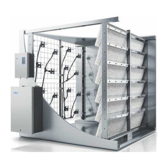
4 - Mounting the central unit --> see chapter 4.3 – Positioning and mounting the central unit 5 - Water installation --> see chapter 4.5 – Water installation 6 - Electrical installation --> see chapter 4.6 – Electrical installation Abb. 1: Installation overview Condair DL Installation... -
Page 11: Installation Of The Humidification Unit
For safety reasons the Condair DL must be installed only in rooms provided with a floor drain. If for some reason the Condair DL must be installed in a location without floor drain, it is mandatory to provide a water tub with drain below the central unit and the duct wall feed throughs and/or water sensors in the room/water tub to safely interrupt water supply in case of leakage. - Page 12 – For control and maintenance purposes we recommend to provide the duct/AHU with an additional inspection door after the post-evaporation unit. – The section of the duct holding the humidification unit must be equipped with a sloping tub having drains before and after the post-evaporation unit (pass-through tub), or with a drain before the separation as well as drains before and after the post-evaporation unit (separated tubs).
-
Page 13: Mounting The Post-Evaporation Unit
4.2.2 Mounting the post-evaporation unit 1. Marking the positions of the fastening elements inside the duct/AHU: • Mark the position of the topmost fastening holes (or welding studs) for the fastening of the lateral supports of the post-evaporation unit “A”, the nozzle system “C” and the fastening profiles for the lateral sealing plates “B”... - Page 14 2. Mount the lateral supports of the post-evaporation unit to the duct walls: • Align the lateral supports with the “TOP” labeled mounting bracket on top with an identical dis- tance to the duct ceiling (target measure ”a”: 65 mm, admissible range: 0...90 mm) and with a distance “b”...
- Page 15 3. Mounting the fastening profiles for the upper sealing plates: • If not done already in step 1, mark the position of the outmost fastening holes for the fastening of the leftmost and rightmost fastening profiles for the upper sealing plates “D” on the duct ceiling using the bended drilling template.
- Page 16 4. Mounting the fastening profiles for the lateral sealing plates: • If not done already with the drilling template in step 1, mark the position of the lateral fastening profiles for the lateral sealing plates on both sides of the duct. Distance between fastening profiles and post-evaporation supports 275 mm.
- Page 17 5. Mount the cross members: Note: This step must be carried out only on air ducts /AHU's with a width >1650 mm. • For air ducts/AHU's with a width >2000 mm the cross members are supplied in sections and must be bolted together on site. Proceed as follows: Undo the screw connections on the cross members overlapping.
- Page 18 6. Mount the vertical support(s): Note: This step must be carried out only on air ducts /AHU's with a width >1650 mm. • For air ducts/AHU's with a height >2000 mm the vertical supports are supplied in sections and must be bolted together on site. Proceed as follows: Undo the screw connections on the vertical supports overlapping.
- Page 19 • Mark horizontal position(s) of the vertical support(s) on the cross members (one vertical sup- port is always in the middle of the duct, several vertical supports must be evenly allocated over the duct width). From the front (view in air flow direction) attach the vertical support(s) with the angle bracket on top to the cross members, then shift upwards until it comes to a stop and fix the vertical support(s) four screws M6 x 16 mm and nuts to the cross members.
- Page 20 7. Mounting the lateral sealing plates: • Start on the bottom shift the lateral sealing plates with the slightly bent surface behind the fasten- ing profiles. Make sure the sealing plates on top of each other covers and overlaps the subjacent sealing plate.
- Page 21 8. Inserting ceramic support profiles: • Insert the ceramic support profiles into the lowest row of holders. Make sure the support profiles are inserted such that the pins on each side of the support profile are outside of the holder. Abb.
- Page 22 9. Mounting the tub rubber sealing: • Fix tub rubber sealing with the clips to the ceramic support profiles as shown below (longer part of the clip is on the side of the rubber sealing). Cut rubber sealing on both sides of the duct to the appropriate length.
- Page 23 10. Inserting ceramic carrier profiles: • Insert the ceramic carrier profiles into holders. Make sure the carrier profiles are inserted such that the pins on each side of the carrier profile are outside of the holder. Abb. 12: Inserting ceramic carrier profiles Installation...
- Page 24 11. Mount the ceramic plates: • Start from the bottom left (view in air flow direction) carefully hang the ceramic plates of the bot- tom row onto the carrier profiles, then align the row to the middle of the duct. Important: Make sure, the very right and very left ceramic plates have the same distance to the duct wall and that all plates properly rest against each other.
- Page 25 12. Mount the upper sealing plates: • Starting on one side push the upper sealing plates underneath the fastening profiles until the they touch the ceramic plates of the topmost row. • Carefully shift the very right and the very left sealing plate against the lateral sealing plates without pushing them away.
-
Page 26: Mounting The Nozzle System
4.2.3 Mounting the nozzle system 1. Mount the lateral supports of the nozzle system to the duct walls: • Align the lateral supports with the “TOP” labeled mounting bracket on top with an identical dis- tance to the duct ceiling (target measure ”a”: 65 mm, admissible range: 0...90 mm) and with a distance “d”... - Page 27 2. Mount the cross members: Note: this step must be carried out only on systems with two nozzle grids in the width. • For air ducts/AHU's with a width >2000 mm the cross members are supplied in sections and must be bolted together on site. Proceed as follows: Undo the screw connections on the cross members overlapping.
- Page 28 3. Mount vertical support(s): Note: This step must be carried out only on air ducts /AHU's with a width >2000 mm. • Mark horizontal position(s) of the vertical support(s) on the cross members. From the back (view in air flow direction) attach the vertical support(s) with the same distance to the duct ceiling as the lateral supports of the nozzle system have, then fix the vertical support(s) four screws M6 x 16 mm and nuts to the cross members.
- Page 29 4. Hang up nozzle grid(s): • Hang up nozzle grid into the holders, then push nozzle grid downwards until its comes to a stop. Repeat step for additional nozzle grid(s) if necessary. Abb. 18: Hang up nozzle grid Installation...
- Page 30 5. Mount housing feed throughs: • Drill holes ø19 mm for the housing feed throughs at the desired position (distance between axes min. 55 mm) into the duct wall, then deburr the holes. Important: It is mandatory that the holes of the housing lead-throughs are below the lowest hose connector on the nozzle grid(s).
- Page 31 6. Connect spray circuits to the housing feed throughs: • Interconnect the spray circuits of the different nozzle grids (if more than on grid is present). Interconnect spray circuits with same colour only. • Connect spray circuits to the appropriate housing feed throughs. Spray circuit 4 (green) Spray circuit 3 (yellow) Spray circuit 2 (blue)
-
Page 32: Positioning And Mounting The Central Unit
Positioning and mounting the central unit Positioning the central unit – The central unit is designed for wall-mounting in interior spaces. Make sure that the construction (duct wall, pillar, etc.) to which the central unit is to be mounted, offers a sufficiently high load-bearing capacity, and is suitable for the installation. - Page 33 Mounting the central unit Central unit 5 " ) . 7 " ( 3 . ( 1 9 Weight: approx. 50 kg 3 " ) ( 6 . Admissible ambient condition: – Ambient temperature: 5 ... 40 °C 3 " ) ( 6 .
-
Page 34: Positioning And Mounting The Control Unit
Positioning and mounting the control unit Positioning the control unit – The control unit is designed for wall-mounting in interior spaces. Make sure that the construction (duct wall, pillar, etc.) to which the control unit is to be mounted, offers a sufficiently high load-bearing capacity, and is suitable for the installation. - Page 35 Mounting the control unit Electrical isolator The electrical isolator (included in the delivery) must be mounted in direct proximity of the control unit (max. distance 1 m) and in a 1 " ) . 4 " convenient height between 0.6 m and 1.9 m (recommended: 1.7 ( 2 .
-
Page 36: Water Installation
Water installation 4.5.1 Overview water installation Central unit Spray circuit connectors ø10 mm arranged on the left or the right side of the central unit Spray circuit lines (con- stant downslope (min. 2%) to central unit) Spray circuit connectors on AHU Spray circuit 4: green RO water connector 12 mm or G 1/2"... -
Page 37: Notes On Water Installation
– Use the supplied black plastic hoses ø10/8 mm and ø12/10 mm only. For hygienic reasons do not use other hoses (except products supplied by your Condair distributor). CAUTION! Fully demineralised water is aggressive. For this reason, the entire water system must contain fully demineralised water resistant material only (do not use copper pipes). - Page 38 – If the conduit length between the water conditioning unit and the central unit of the Condair DL exceeds 20 m, the supply conduit must be equipped with a suitable pressure damper (overflow valve, surge tank, etc.). Furthermore, the supply conduit must be properly fastened according to the regulations –...
-
Page 39: Electrical Installation
DANGER! Danger of electric shock The control unit of the adiabatic air humidification system Condair DL is mains powered. Live parts may be exposed when the control unit is open. Touching live parts may cause severe injury or danger to life. -
Page 40: Wiring Diagram Condair Dl
4.6.2 Wiring diagram Condair DL Installation... -
Page 41: Electrical Connections Between Central Unit And Control Unit
4.6.3 Electrical connections between central unit and control unit 4.6.3.1 Wiring diagram central unit - control unit Control unit Driver Control board board 24V E (6.3 AT) (630 mAT) 24V E CR2032 D– Error Service Running Unit On D– 1 2 3 4 5 6 9 10 24V IC... -
Page 42: Installation Work Central Unit - Control Unit
4.6.3.2 Installation work central unit - control unit Connecting the motor cable (MC) to the frequency converter (type A only) Ex factory the motor cable is connected to the frequency converter inside control unit. On site the motor cable must be fed via the cable gland (top left) into the central unit, and there be connected to the booster pump motor according to the wiring diagram. - Page 43 Connecting the cable harness “valves” (CH2) Ex factory the cable harness “valves” (CH2) is connected inside central unit to the corresponding valves. On site the terminal connectors of the cable harness must be connected to the appropriate terminals (X3 to X6) on the driver board inside the control unit.
- Page 44 Connecting the cable harness “Ag-Ionisation” and ”Conductivity measuring” (CH3) Ex factory the cable harness “Ag-Ionisation” and ”Con- ductivity measuring” (CH3) is connected inside central unit to the silver ionisation cartridge and to the conductiv- ity sensor. On site the terminal connectors of the cable harness must be connected to the appropriate terminals on the Ag-Ion board (X18) and on the conductivity board (X17) inside the control unit.
-
Page 45: External Electrical Connections
Cable bridge, if no monitoring devices are connected to SC1 and SC2 Jumper for activating the terminating resistor for Modbus network (Jumper must be connected, if Condair DL is the last unit in the Modbus network) Abb. 26: Wiring diagram external electrical connections... -
Page 46: Installation Work External Connections
4.6.4.2 Installation work external connections Connecting the external safety chain The potential-free contacts of external moni t or ing de- vices (e.g. ventilation interlock, safety high limit humi- distat, airflow monitor, etc.) are connected in series (safety chain “K1”) to the terminals “SC1” and “SC2” of the terminal block “X1”... - Page 47 Running Unit On has expired. 9 10 – “Running”: This relay closes as soon as the Condair DL hu- midifies. Control unit – “Unit on”: This relay closes as soon as the voltage supply to the control unit of the Condair DL is switched on.
-
Page 48: Connecting Options
If problems should arise when operating the system in conjunction with a fault current protection switch, please contact your Condair representative. 4.6.5 Connecting options For the electrical connection of options (e.g. leakage monitoring) please refer to the separate manual of corresponding option. - Page 49 Notes...
- Page 50 Notes...
- Page 52 CONSULTING, SALES AND SERVICE: Condair Ltd. Talstrasse 35-37, CH-8808 Pfäffikon Phone +41 55 416 61 11, Fax +41 55 416 62 62 info@condair.com, www.condair.com...
Need help?
Do you have a question about the DL and is the answer not in the manual?
Questions and answers