Advertisement
Quick Links
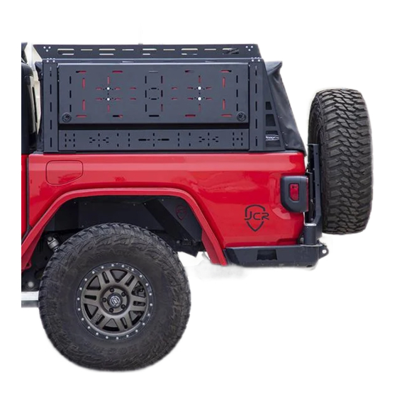
JT
OV E R L A N D B ED R AC K
IN S TA L L I NS TRU C T I O N S
Please read the mounting instructions below carefully before attempting to install.
Be sure to check out the install video on the product page, if available.
Thank you for purchasing from JcrOffroad! Checkout our website, www.jcroffroad.com for other great off-road
products. Be sure to rate and review our product online. If you have any questions or are missing parts, please
don't hesitate to call us at 269-353-1184!
Advertisement

Subscribe to Our Youtube Channel
Related Manuals for JCROffroad JT OVERLAND BED RACK


Summary of Contents for JCROffroad JT OVERLAND BED RACK
- Page 1 Be sure to check out the install video on the product page, if available. Thank you for purchasing from JcrOffroad! Checkout our website, www.jcroffroad.com for other great off-road products. Be sure to rate and review our product online. If you have any questions or are missing parts, please...
-
Page 2: I Nc Lu D E D Ha R Dwar E
I NC LU D E D HA R DWAR E 5/16”-18 5/16”-18 X 3/4" 5/16”-18 X 1" Nylock Nut Button Head Button Head 5/16”-18 Flanged Nylock Nut 5/16”-18 X 1-1/2” Carriage Bolt 10-24 X 3/4” Button Head M8 X 1.25mm Nylock Nut 5/16”... -
Page 3: Included Parts
INCLUD ED PARTS 1L/1R... - Page 4 I N CLUD E D PARTS 1L/1R 1L/1R 1L/1R 1L/1R...
- Page 5 ASSE M BLY Start by loosely mounting the top rail to the corresponding front and rear legs using the 5/16”-18 x 3/4” button head bolts and 5/16”-18 serr. flange nuts. The side rail should sit on the top of the legs with the small slotted flange pointing down along the side of the legs.
- Page 6 AS SE M BLY Next, mount two of the wider bars between the front and rear legs using the 5/16”-18 x 3/4” button head bolts, 1/4” washers and 5/16”-18 serr. flange nuts. You will see that there are several mounting options for this bar.
- Page 7 AS SE M BLY Next, connect the two sides you assembled together using the thinner cross bars with 5/16”-18 x 3/4” button head bolts and 5/16”-18 serr. flange nuts to mount them in position. One bar will mount to the front of the top rail, and one will mount to the rear.
- Page 8 A SS E M BLY Next, mount the two remaining wider bars to the top of the rack between the bars you just installed. Do this using the 5/16”-18 x 3/4” button head bolts and 5/16”-18 serr. flange nuts. Which slots you mount them to is up to you and what you plan to use them for.
- Page 9 A SS E M BLY With the rack assembled, you can place it onto the bed of your vehicle. How you mount it depends on whether or not you have the trail rail system in the bed of your Gladiator. If you do, simply insert a 5/16”-18 x 1-1/2”...
- Page 10 AS SE M BLY If you do not have the trail rail, you will need to clamp the legs to the bed, to do so, loosely attach the c shaped bracket to the back of the bottom of each of the legs using the 5/16”-18 x 1-1/2” carriage bolts and 5/16”-18 flanged nylock nuts.
- Page 11 A SS E MB LY With the rack and soft topper in place, you can install the corner support brackets using the 5/16”-18 x 3/4” button head bolts and 5/16”-18 serr. flange nuts. The rear bracket is the one with the hole cut out of the middle of it.
- Page 12 ASSEMBLY Next you can get started on installing the doors if you are choosing to do so. Start by installing the triangular hinge brackets into the slots necessary for where you want your doors on the inside of the legs using the 5/16”-18 x 3/4”...
- Page 13 A SS E MB LY Next, mount the latch brackets roughly where the latch of the door will land when closed. You will most likely need to move them later so just get them in the general area. The latch brackets should be positioned so that when they are bolted into place, the other side sticks in towards the door and then out towards the outside of the rack.
- Page 14 A SS E M BLY Next, mount the latches to the holes in the doors. To do this, start by removing the metal back cover from the latch. Then, put the latch into the hole in the door through the front and place the metal back piece back onto the latch from the inside of the door, sandwiching the door between them.
- Page 15 A SS E M BLY Next, mount the doors to the hinges using the 5/16”-18 x 3/4” button head bolts, 5/16” nylon washers and 5/16”-18 nylock nuts. The door bolts in between the hinges with a nylon washer between the hinge and the door as well as the door and the nut.
- Page 16 A SS E MB LY Next, attach either the gas struts or the lanyards depending on which way your door is going to open. If it is going to open up, you will need to attach the gas struts (step 13). If it is going to open down, you will need to attach the lanyards (step 14).
- Page 17 ASSE M BLY For the door opens down, attach one end of the lanyard to the hole in the middle of the leg using a 10-24 X 3/4” button head bolt, a #10 nylon washer and a 10-24 nylock nut. Then attach the other end to the inside of the door using the same hardware.
- Page 18 A SS E MB LY Next, if you have installed a soft topper, undo the nuts on the bolts for the clamps on leg. Next, place the hook shaped soft topper bracket into the hole in the rail of the soft topper and hold the other soft topper bracket underneath it so that the holes on the two line up and the carriage bolts go through the slots in the bottom bracket.
- Page 19 D IME N S IO N S...
Need help?
Do you have a question about the JT OVERLAND BED RACK and is the answer not in the manual?
Questions and answers