Table of Contents
Advertisement
Quick Links
Advertisement
Table of Contents

Related Manuals for KLING & FREITAG SPECTRA 212i Wall Arm


Summary of Contents for KLING & FREITAG SPECTRA 212i Wall Arm
- Page 1 EN | VERSION 1.1 | 06/17/21 USER‘S MANUAL K&F SPECTRA 212i Wall Arm...
-
Page 3: Table Of Contents
User‘s Manual K&F SPECTRA 212i Wall Arm Table of Content Chapter / Content Page Introduction 1.1 Icons Used 1.2 About this user's manual 1.3 Scope of Application Product Description 2.1 Variants 2.2 Intended Use 2.3 Items included (L and S versions) 2.4 Components... -
Page 4: Introduction
User's Manual K&F SPECTRA 212i Wall Arm SPECTRA 212i Wall Arm 17.06.2021 06/17/21 Introduction K&F SPECTRA 212i Wall Arm Icons Used This icon indicates a risk of injury or death. Not following these instructions may result in seri- WARNING ous health problems including potentially fatal injuries. -
Page 5: Product Description
User's Manual K&F SPECTRA 212i Wall Arm Product Description The wall arm allows for vertical wall installation of 1 K&F SPECTRA 212i speaker or for hori- zontal wall installation of up to 2 K&F SPECTRA 212i speakers. The following installation options are available:... -
Page 6: Variants
User's Manual K&F SPECTRA 212i Wall Arm SPECTRA 212i Wall Arm 17.06.2021 06/17/21 Variants The wall arm is available with either an S (short) or L (long) boom. The two variants differ in boom length. Wall Arm L Wall Arm S... -
Page 7: Components
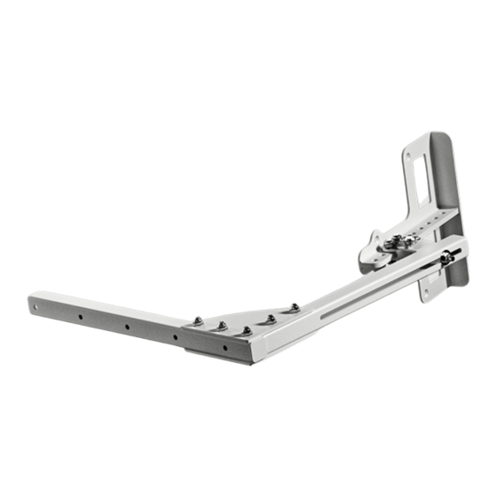
User's Manual K&F SPECTRA 212i Wall Arm Components Wall arm: wall profile Wall arm: support plate Wall arm: boom Swivel mount Split pin with linch pin Load Adapter Install Screw connection SPECTRA 212i Flying Frame © KLING & FREITAG GMBH Version 1.1... -
Page 8: Technical Specifications
User's Manual K&F SPECTRA 212i Wall Arm SPECTRA 212i Wall Arm 17.06.2021 06/17/21 Technical Specifications 2.5.1 Overview 2 SPECTRA 212i speakers (max.), flying frame, and Load capacity mounting accessories Wall arm (S): 7.1 kg Weight Wall arm (L): 7.9 kg... -
Page 9: Wall Arm (S) Dimensions
User's Manual K&F SPECTRA 212i Wall Arm 2.5.3 Wall Arm (S) Dimensions 405 mm [15.945 inch] 40 mm [1.575 inch] 190 mm [7.48 inch] © KLING & FREITAG GMBH Version 1.1 Page 9 of 15... -
Page 10: Flying Frame Dimensions
User's Manual K&F SPECTRA 212i Wall Arm SPECTRA 212i Wall Arm 17.06.2021 06/17/21 2.5.4 Flying Frame Dimensions 9 x 30mm(=270 mm) [10.63 inch] 30 mm [1.181 inch] 321.6 mm [12.66 inch] 322.5 mm [12.697 inch] 152.4 mm [6.002 inch] Refer to our website at http://www.kling-freitag.de for a detailed dimensional drawing. -
Page 11: Safety Instructions
User's Manual K&F SPECTRA 212i Wall Arm Safety Instructions Risks imposed by falling or overturning parts WARNING • Be sure to install, suspend, fasten, and use Kling & Freitag speaker accessories only using the designated fixtures as specified in this document. -
Page 12: Installation
User's Manual K&F SPECTRA 212i Wall Arm SPECTRA 212i Wall Arm 17.06.2021 06/17/21 Installation Required Tools Required Tools Required mounting material IS5 hexagon socket wrench for mounting the Suitable wall anchors with corresponding ac- flying frame on the speaker cessories. The wall-anchor screw must not ex- ceed a maximum diameter of 10 mm. - Page 13 User's Manual K&F SPECTRA 212i Wall Arm 4. Screw the boom with the sup- port plates to the wall profile. 5. Hand-tighten all five bolt con- nections on the support plates. 6. Remove the linch pin from the split pin [B].
- Page 14 User's Manual K&F SPECTRA 212i Wall Arm SPECTRA 212i Wall Arm 17.06.2021 06/17/21 8. Place the speaker unit with the premounted flying frame on a suitable lift. To facilitate attachment, we rec- ommend using a lift with an ac- cessible platform.
-
Page 15: Maintenance
User's Manual K&F SPECTRA 212i Wall Arm Maintenance • Perform a visual inspection before each installation. • Visually inspect the entire setup every six months. • When performing those checks, particularly look for deformations, cracks, dents, damage to threads, and corrosion. Also check slings and lifts (e.g. shackles, chains, and steel ropes) carefully for wear and deformation. - Page 16 THANK CHOOSING K&F. KLING & FREITAG GmbH Junkersstrasse 14 · D-30179 Hannover Phone +49 (0)511 969970 www.kling-freitag.de · info@kling-freitag.de...
Need help?
Do you have a question about the SPECTRA 212i Wall Arm and is the answer not in the manual?
Questions and answers