KLING & FREITAG CA 1215 User Manual
Hide thumbs
Also See for CA 1215:
- User manual (54 pages) ,
- User manual (51 pages) ,
- User manual (9 pages)
Table of Contents
Advertisement
Quick Links
Advertisement
Table of Contents

Related Manuals for KLING & FREITAG CA 1215


Summary of Contents for KLING & FREITAG CA 1215
- Page 1 KLING FREITAG CA 1201, CA 1215, CA 1515 & Version 4.2 User's Manual Stand: 07.05.2015 Important Information, Please Read Before Use! KLING FREITAG GmbH & Junkersstrasse 14 D-30179 Hannover PHONE 0 (049) 511- 969 97-0 FAX 0 (049) 511- 67 37 94...
-
Page 2: Table Of Contents
User's Manual CA 1201, CA 1215-6 /-9, CA 1515-6 /-9 Contents Inhaltsverzeichnis Introduction 1. 1. 1. 1. 2. 2. 2. 2. Symbols in User's Manual Information about this User's Manual 3. 3. 3. 3. General Instructions for Using Speakers 4. 4. 4. 4. -
Page 3: Introduction
CA 1201, CA 1215-6 and CA 1215-9 18.2 CA 1201-M, CA 1215-6-M and CA 1215-9-M 18.3 CA 1201, CA 1215-6 and CA 1215-9 with Option ‘Installation’ 18.4 CA 1515-6 and CA 1515-9 18.5 CA 1515-6 and CA 1515-9 with Option ‘Installation’... -
Page 4: Symbols In User's Manual
Important 3. 3. 3. 3. Information about this User's Manual User's Manual CA 1201, CA 1215-6 /-9, CA 1515-6 /-9 Version 4.2, 07.05.2015 © by André Figula, Kling & Freitag GmbH, 1998 - 2015; all rights reserved. All specifications in this manual are based on information available at the time of publishing for the features and safety guidelines of the described products. -
Page 5: General Instructions For Using Speakers
User's Manual CA 1201, CA 1215-6 /-9, CA 1515-6 /-9 4. 4. 4. 4. General Instructions for Using Speakers Mounting the speakers Mounting the speakers Mounting the speakers Mounting the speakers To prevent injury, the speakers must be securely placed on the floor or secured to the wall according to the instructions on page 17 (Mounting Instructions for Speakers). - Page 6 User's Manual CA 1201, CA 1215-6 /-9, CA 1515-6 /-9 If power amplifiers have power ratings lower than mentioned above, then it is imperative that a clipping limiter is used to protect the speaker even if it is used with a Kling & Freitag system controller.
-
Page 7: Product Descriptions And Versions
User's Manual CA 1201, CA 1215-6 /-9, CA 1515-6 /-9 5. 5. 5. 5. Product Descriptions and Versions 5.1 CA 1201 Short description: Short description: Short description: Short description: 2-way full-range speaker system with 12" low-mid chassis and 1" high frequency driver on a rotatable 90° x 60°... -
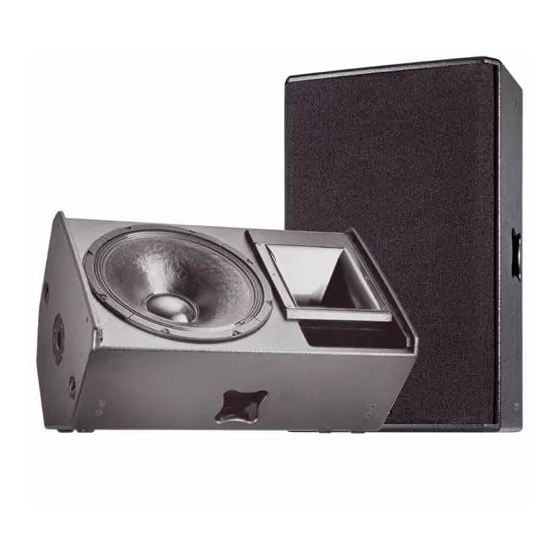
Page 8: Ca 1215-6
− Versions for outdoor use under roofs CA 1215-6-SP: − Version with integrated power amplifier technology (not for CA 1215-6-M) 'SP' speakers are shipped with a separate user's manual! Special finish in RAL colours − KLING & FREITAG GMBH ©1998 - 2015Version 4.0, 07.05.2015... - Page 9 − Version for outdoor use under roofs CA 1215-9-SP: − Version with integrated power amplifier technology (not for CA 1215-9-M) 'SP' speakers are shipped with a separate user's manual! Special finish in RAL colours − KLING & FREITAG GMBH ©1998 - 2015Version 4.0, 07.05.2015...
- Page 10 User's Manual CA 1201, CA 1215-6 /-9, CA 1515-6 /-9 5.4 CA 1515-6 Short description: Short description: Short description: Short description: 2-way high-performance speaker system with 15" low-mid chassis and 1.5" high frequency driver on a rotat- able 65° x 50° CD horn. Homogeneous coverage and constant directivity starting at 1.2 kHz. Integrated cross- over with self-resetting protection circuit for chassis and crossover, delay time and phase optimisation.
- Page 11 User's Manual CA 1201, CA 1215-6 /-9, CA 1515-6 /-9 5.5 CA 1515-9 Short description: Short description: Short description: Short description: 2-way high-performance speaker system with 15" low-mid chassis and 1.5" high frequency driver on a rotat- able 90° x 50° CD horn. Homogeneous coverage and constant directivity starting at 1.0 kHz. Integrated cross- over with self-resetting protection circuit for chassis and crossover, delay time and phase optimisation.
-
Page 12: Important Notes For The Options 'Outdoor' And 'Installation
User's Manual CA 1201, CA 1215-6 /-9, CA 1515-6 /-9 6. 6. 6. 6. Important Notes for the Options ‘Outdoor’ and ‘Installation’ Speakers with the option ‘Outdoor Mobile’ and ‘Outdoor Installation’ have been opti-mised for outdoor use. They withstand temperature fluctuations in moderate climate zones and do not accumulate condensation water. -
Page 13: Notes For Versions With '100V' Option
User's Manual CA 1201, CA 1215-6 /-9, CA 1515-6 /-9 7. 7. 7. 7. Notes for Versions with ‘100V’ Option Kling & Freitag speakers with ‘100V’ option are fitted with high-quality toroidal trans-formers. This serves to minimize loss of sound. Highly professional sound reinforcement results can be achieved using 100 V Kling &... -
Page 14: Instructions For Suspending The Speakers
User's Manual CA 1201, CA 1215-6 /-9, CA 1515-6 /-9 8. 8. 8. 8. Instructions for Suspending the Speakers The speake The speakers may only be suspended by trained specialised personnel. rs may only be suspended by trained specialised personnel. -
Page 15: Using The 'Allsafe Jungfalk' Flying Points
User's Manual CA 1201, CA 1215-6 /-9, CA 1515-6 /-9 There are several flying options, if you use a K&F U-Mount or K&F ceiling bracket. These mounts are designed specifically for each speaker systems. For further information, please contact our local dealer. -
Page 16: Coverage Patterns Of The Ca Speakers
User's Manual CA 1201, CA 1215-6 /-9, CA 1515-6 /-9 9. 9. 9. 9. Coverage Patterns of the CA Speakers The mid-high systems can be operated in a vertical or horizontal (i.e. as a stage monitor) position. The cover- age pattern of the speakers can be adapted to special needs by a 90° rotatable horn. -
Page 17: Mounting Instructions For Speakers
User's Manual CA 1201, CA 1215-6 /-9, CA 1515-6 /-9 10. Mounting Instructions for Speakers Mount the speakers securely. To avoid injury or damage, always be sure to mount the speakers securely so that they do not fall. Speakers, which are stacked, must be secured with securing straps. -
Page 18: Arrayed Speaker Systems (Cluster)
*If several 90° systems are clustered, unwanted interference effects may appear. As a result, we do not gen- erally recommend clustered configurations of CA 1201, CA 1215-9 and CA 1515-9 systems. If wide angles are to be covered, we recommend the use of several 60° or 65° systems in one cluster. -
Page 19: With Rotated Horn
User's Manual CA 1201, CA 1215-6 /-9, CA 1515-6 /-9 10.2.2 With rotated Horn Winkel 2 Horn Winkel 3 rotated Standing speaker Winkel 1 A smaller angle 3 results in a smaller vertical cov- erage angle but increases the sound power level. -
Page 20: Wiring
User's Manual CA 1201, CA 1215-6 /-9, CA 1515-6 /-9 11. Wiring The speaker is equipped with two parallel Speakon connectors. Make sure that all units are switched off and all controls are turned down before connecting your CA systems. -
Page 21: Avoiding Ground Loops
User's Manual CA 1201, CA 1215-6 /-9, CA 1515-6 /-9 11.2 Avoiding Ground Loops 11.2.1 What is a Ground Loop? Every component of a P.A. or Hi-Fi System has its own internal 0 V reference (ground). This point is often con- nected to the protective earth connector (PE / Ground). -
Page 22: Configurations And Connecting Diagrams
User's Manual CA 1201, CA 1215-6 /-9, CA 1515-6 /-9 12. Configurations and Connecting Diagrams 12.1 Operating the Systems without K&F System Controller The full-range systems can be used alone or in conjunction with a K&F subwoofer with integrated crossover (e.g. SW 112-XO / SW 115D-XO SW 115E-XO or SW 118E-XO). In this mode of operation the crossover limits the subwoofer's frequency range. -
Page 23: Full Range Mode & Subwoofer With Crossover (Xo)
User's Manual CA 1201, CA 1215-6 /-9, CA 1515-6 /-9 12.1.2 Full Range Mode & Subwoofer with Crossover (XO) In this mode of operation you can easily realise applications, where a higher bass level is needed. In this mode of operation be sure to use only amplifiers, which can handle speaker im- 3 •. -
Page 24: Operations With K&F System Controller
User's Manual CA 1201, CA 1215-6 /-9, CA 1515-6 /-9 12.2 Operations with K&F System Controller For optimal performance and operating safety we recommend using a K&F system controller. Instructions for use, connecting diagrams and detailed descriptions of the latest controller models ‘CD 24’ and ‘CD 44’ you can find in the corresponding user’s manuals. -
Page 25: Crossovers
User's Manual CA 1201, CA 1215-6 /-9, CA 1515-6 /-9 14. Crossovers 14.1 Wiring Diagram CA 1201 The crossover networks as of the end of 2003 differ from earlier models. Please compare the crossover built into your speaker with the figures below and wire accordingly: 14.1.1 Version A... -
Page 26: Version B
User's Manual CA 1201, CA 1215-6 /-9, CA 1515-6 /-9 14.1.2 Version B CA 1201 & CA 1201-M from serial no. 231 0000 20 30 (as of the end of October 03) Pin assignment Speakon NL4 ‘IN’ ‘OUT’ parallel with ‘IN’... -
Page 27: Wiring Diagram Ca 1215-6 And Ca 1215 -9
14.2.1 Version A CA 1215-6 and CA 1215-6-M up to serial number 23090007055 (before Sept. 03) CA 1215-9 and CA 1215-9-M up to serial number 23090002675 (before Sept. 03) IN + / link to XO 2... -
Page 28: Version B
CA 1201, CA 1215-6 /-9, CA 1515-6 /-9 14.2.2 Version B CA 1215-6 and CA 1215-6-M from serial number 23090007056 up (as of Sept. 03) CA 1215-9 and CA 1215-9-M from serial number 23090002676 up (as of Sept. 03) IN + / link to XO 2... -
Page 29: Wiring Diagram Ca 1515-6 And Ca 1515-9
User's Manual CA 1201, CA 1215-6 /-9, CA 1515-6 /-9 14.3 Wiring Diagram CA 1515-6 and CA 1515-9 The crossover networks as of the end of 2003 differ from earlier models. Please compare the crossover built into your speaker with the figures below and wire accordingly. -
Page 30: Version B
User's Manual CA 1201, CA 1215-6 /-9, CA 1515-6 /-9 14.3.2 Version B CA 1515-6 and CA 1515-9 from serial number 23116000435 (as of November 03) IN + / link to XO 2 IN - / Link to XO 2 Pin assignment Speakon NL4 ‘IN’... -
Page 31: Technical Specifications
User's Manual CA 1201, CA 1215-6 /-9, CA 1515-6 /-9 16. Technical Specifications 16.1 CA 1201 Loudspeaker Design 2-way passive system, bass reflex tuning Frequency range -10 dB 54 Hz - 19 kHz Frequency range ±3 dB 65 Hz - 18 kHz Coverage angles nominal 90°... - Page 32 User's Manual CA 1201, CA 1215-6 /-9, CA 1515-6 /-9 16.2 CA 1215-6 Loudspeaker Design 2-way passive system, bass reflex tuning Frequency range -10 dB 62 Hz - 22 kHz Frequency range ±3 dB 84 Hz - 19 kHz Coverage angles nominal 65°...
-
Page 33: Ca 1215-9
User's Manual CA 1201, CA 1215-6 /-9, CA 1515-6 /-9 16.3 CA 1215-9 Loudspeaker Design 2-way passive system, bass reflex tuning Frequency range -10 dB 58 Hz - 22 kHz Frequency range ±3 dB 80 Hz - 19 kHz Coverage angles nominal 90°... -
Page 34: Ca 1515-6
User's Manual CA 1201, CA 1215-6 /-9, CA 1515-6 /-9 16.4 CA 1515-6 Loudspeaker Design 2-way passive system, bass reflex tuning Frequency range -10 dB 47 Hz - 22 kHz Frequency range ±3 dB 77 Hz - 19 kHz Coverage angles nominal 65°... -
Page 35: Ca 1515-9
User's Manual CA 1201, CA 1215-6 /-9, CA 1515-6 /-9 16.5 CA 1515-9 Loudspeaker Design 2-way passive system, bass reflex tuning Frequency range -10 dB 58 Hz - 22 kHz Frequency range ±3 dB 75 Hz - 19 kHz Coverage angles nominal 90°... -
Page 36: Measuring Charts
User's Manual CA 1201, CA 1215-6 /-9, CA 1515-6 /-9 17. Measuring Charts 17.1 CA 1201 Frequency response Frequency response Impedance 31.6 3,16 1000 10000 20000 Frequency (Hz) Horizontal Beamwidth Vertical 1000 10000 20000 Frequency (Hz) Directivity 1000 10000 20000 Frequency (Hz) KLING &... - Page 37 User's Manual CA 1201, CA 1215-6 /-9, CA 1515-6 /-9 Horizontal coverage 180° 150° 120° 90° 60° Attenuation (dB) 30° < 3 0° 3 - 6 -30° 6 - 9 -60° 9 - 12 -90° 12 - 15 -120° 15 - 18 -150°...
- Page 38 User's Manual CA 1201, CA 1215-6 /-9, CA 1515-6 /-9 17.2 CA 1215-6 Frequency response Frequency response Impedance 31.6 3,16 1000 10000 20000 Frequency (Hz) Horizontal Beamwidth Vertical 1000 10000 20000 Frequency (Hz) Directivity 1000 10000 20000 Frequency (Hz) KLING & FREITAG GMBH ©1998 - 2015Version 4.0, 07.05.2015...
- Page 39 User's Manual CA 1201, CA 1215-6 /-9, CA 1515-6 /-9 Horizontal coverage 180° 150° 120° 90° 60° Attenuation (dB) 30° < 3 0° 3 - 6 -30° 6 - 9 -60° 9 - 12 -90° 12 - 15 -120° 15 - 18 -150°...
- Page 40 User's Manual CA 1201, CA 1215-6 /-9, CA 1515-6 /-9 17.3 CA 1215-9 Frequency response Frequency response Impedance 31.6 3,16 1000 10000 20000 Frequency (Hz) Horizontal Beamwidth Vertical 1000 10000 20000 Frequency (Hz) Directivity 1000 10000 20000 Frequency (Hz) KLING & FREITAG GMBH ©1998 - 2015Version 4.0, 07.05.2015...
- Page 41 User's Manual CA 1201, CA 1215-6 /-9, CA 1515-6 /-9 Horizontal coverage 180° 150° 120° 90° 60° Attenuation (dB) 30° < 3 0° 3 - 6 -30° 6 - 9 -60° 9 - 12 -90° 12 - 15 -120° 15 - 18 -150°...
- Page 42 User's Manual CA 1201, CA 1215-6 /-9, CA 1515-6 /-9 17.4 CA 1515-6 Frequency response Frequency response Impedance 31.6 3,16 1000 10000 20000 Frequency (Hz) Horizontal Beamwidth Vertical 1000 10000 20000 Frequency (Hz) Directivity 1000 10000 20000 Frequency (Hz) KLING & FREITAG GMBH ©1998 - 2015Version 4.0, 07.05.2015...
- Page 43 User's Manual CA 1201, CA 1215-6 /-9, CA 1515-6 /-9 Horizontal coverage 180° 150° 120° 90° 60° Attenuation (dB) 30° < 3 0° 3 - 6 -30° 6 - 9 -60° 9 - 12 -90° 12 - 15 -120° 15 - 18 -150°...
- Page 44 User's Manual CA 1201, CA 1215-6 /-9, CA 1515-6 /-9 17.5 CA 1515-9 Frequency response Frequency response Impedance 3,16 1000 10000 20000 Frequency (Hz) Horizontal Beamwidth Vertical 1000 10000 20000 Frequency (Hz) Directivity 1000 10000 20000 KLING & FREITAG GMBH ©1998 - 2015Version 4.0, 07.05.2015...
- Page 45 User's Manual CA 1201, CA 1215-6 /-9, CA 1515-6 /-9 Horizontal coverage 180° 150° 120° 90° 60° Attenuation (dB) 30° < 3 0° 3 - 6 -30° 6 - 9 -60° 9 - 12 -90° 12 - 15 -120° 15 - 18 -150°...
-
Page 46: Dimensions
User's Manual CA 1201, CA 1215-6 /-9, CA 1515-6 /-9 18. Dimensions 18.1 CA 1201, CA 1215-6 and CA 1215-9 189.3 mm [7.451 inch] pole mount K&M 19656 Rigging Points 183.2 mm ANCRA Jungfalk [7.211 inch] 120030-31 378.5 mm 375 mm 189.3 mm... -
Page 47: Ca 1201-M, Ca 1215-6-M And Ca 1215-9-M
User's Manual CA 1201, CA 1215-6 /-9, CA 1515-6 /-9 18.2 CA 1201-M, CA 1215-6-M and CA 1215-9-M 189.3 mm [7.451 inch] Plastic Sliders Rigging Points pole mount ANCRA Jungfalk K&M 19656 120030-31 378.5 mm 374.1 mm 174.1 mm [14.903 inch] [14.729 inch]... -
Page 48: Ca 1201, Ca 1215-6 And Ca 1215-9 With Option 'Installation
User's Manual CA 1201, CA 1215-6 /-9, CA 1515-6 /-9 18.3 CA 1201, CA 1215-6 and CA 1215-9 with Option ‘Installation’ 189.3 mm [7.451 inch] 183.2 mm 7 x Rigging Point M 10 [7.211 inch] 378.5 mm 375 mm 189.3 mm [14.903 inch]... -
Page 49: Ca 1515-6 And Ca 1515-9
User's Manual CA 1201, CA 1215-6 /-9, CA 1515-6 /-9 18.4 CA 1515-6 and CA 1515-9 216.8 mm [8.536 inch] Plastic Sliders pole mount Rigging Points K&M 19656 ANCRA Jungfalk 120030-31 433.6 mm 411.3 mm 212.3 mm [17.073 inch] [16.195 inch] [8.358 inch]... -
Page 50: Ca 1515-6 And Ca 1515-9 With Option 'Installation
User's Manual CA 1201, CA 1215-6 /-9, CA 1515-6 /-9 18.5 CA 1515-6 and CA 1515-9 with Option ‘Installation’ 216.8 mm [8.536 inch] 7 x Rigging Point M10 433.6 mm 411.3 mm 212.3 mm [17.073 inch] [16.195 inch] [8.358 inch] 73°... -
Page 51: Accessories For The Ca Systems
User's Manual CA 1201, CA 1215-6 /-9, CA 1515-6 /-9 18.6 Accessories for the CA Systems Tilt bracket CA 1201/CA1215 Cradle 1201/CA1215 CA 1515 Cradle 1515 Multi Cradle CA 1201/CA1215 Wall mount, Multi Cradle CA 1515 tiltable up to 50 kg Mounting bracket for versions with option ‚Installation’... - Page 52 User's Manual CA 1201, CA 1215-6 /-9, CA 1515-6 /-9 Tilt Bracket Stand Adapter Distance Rod Distance rod & application examples TV-clamp TV-spigot single stud with tilt bracket fitting Further information is available in our downloadable catalogue at: KLING & FREITAG GMBH ©1998 - 2015Version 4.0, 07.05.2015...
-
Page 53: Kling & Freitag Gmbh ©1998 - 2015Version 4.0, 07.05.2015
User's Manual CA 1201, CA 1215-6 /-9, CA 1515-6 /-9 19. Disposal Please recycle the packaging material of the device. 19.1 Germany It is not allowed to dispose of used electrical equipment as domestic waste. It is not allowed to dispose of used electrical equipment as domestic waste.
Need help?
Do you have a question about the CA 1215 and is the answer not in the manual?
Questions and answers