KLING & FREITAG CA 1201 User Manual
Hide thumbs
Also See for CA 1201:
- User manual (54 pages) ,
- User manual (9 pages) ,
- User manual (12 pages)
Table of Contents
Advertisement
Quick Links
See also:
User Manual
K&F CA 1201, CA 1215, CA 1515
Die Version CA 106 F weicht in Form und Aussehen von
User's Manual
Benutzerhandbuch
Important Information,
Please Read Before Use!
KLING & FREITAG GmbH
Junkersstrasse 14
D-30179 Hannover
PHONE +49 (0) 511- 96 99 70
TEL 0 (049) 511- 969 97-0
FAX
+49 (0) 511- 67 37 94
www.kling-freitag.de
dieser Abbildung ab.
Released: 22.03.2006
Stand: 08.06.2006
Version 3.0.
Version 1.0
Advertisement
Table of Contents

Subscribe to Our Youtube Channel
Related Manuals for KLING & FREITAG CA 1201


Summary of Contents for KLING & FREITAG CA 1201
- Page 1 K&F CA 1201, CA 1215, CA 1515 Die Version CA 106 F weicht in Form und Aussehen von dieser Abbildung ab. Version 3.0. Version 1.0 User‘s Manual Benutzerhandbuch Released: 22.03.2006 Stand: 08.06.2006 Important Information, Please Read Before Use! KLING & FREITAG GmbH...
- Page 2 User's Manual CA 1201, CA 1215-6 /-9, CA 1515-6 /-9 KLING & FREITAG GMBH ©1998 - 2006 Version 3.0, 22.03.2006 Page 2 of 51...
- Page 3 Important Information about this User's Manual User's Manual CA 1201, CA 1215-6 /-9, CA 1515-6 /-9 Version 3.0, 22.03.2006 © by André Figula, Kling & Freitag GmbH, 1998 - 2006; all rights reserved. All specifications in this manual are based on information available at the time of pub- lishing for the features and safety guidelines of the described products.
-
Page 4: Table Of Contents
User's Manual CA 1201, CA 1215-6 /-9, CA 1515-6 /-9 Contents Chapter Page General Instructions for Using Speakers Product Descriptions and Versions CA 1201 CA 1215-6 CA 1215-9 CA 1515-6 CA 1515-9 Important Notes for the ‘Outdoor’ Option ‘Outdoor Mobile’... - Page 5 User's Manual CA 1201, CA 1215-6 /-9, CA 1515-6 /-9 Chapter Page 11. Crossovers 11.1 Wiring Diagram CA 1201 11.1.1 Version A 11.1.2 Version B 11.2 Wiring Diagram CA 1215-6 and CA 1215 -9 11.2.1 Version A 11.2.2 Version B 11.3 Wiring Diagram CA 1515-6 and CA 1515-9...
-
Page 6: General Instructions For Using Speakers
− Integrated or preceding subsonic filter (approx. 20 Hz, min. 12 dB / octave) − integrated clipping limiter − for speaker models CA 1201 or CA 1215: Warning Ω Ω... -
Page 7: Preventing Hearing Damage
User's Manual CA 1201, CA 1215-6 /-9, CA 1515-6 /-9 The following signals may damage the speakers − Permanent high-pitched signals with high frequency, and continuous noise from feedback. − Permanently distorted signals with high power. − Noises, which occur when the amplifier is on while equipment is being con- Important nected, disconnected or switched on. -
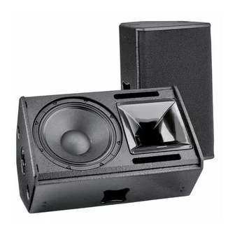
Page 8: Product Descriptions And Versions
Enclosure with additional monitor angle − CA 1201-100V: 100V version with 300 VA toroidal transformer − CA 1201 -- - ‘Outdoor Installation’ / ‘Outdoor Mobile’ Versions for outdoor use under roofs − CA 1201-SP: Version with integrated power amplifier technology (not for CA 1201-M) 'SP' speakers are shipped with a separate user's manual! −... -
Page 9: User's Manual Ca 1201, Ca 1215-6 /-9, Ca 1515-6
User's Manual CA 1201, CA 1215-6 /-9, CA 1515-6 /-9 2.2 CA 1215-6 Short description: 2-way high-performance speaker system with 12" low-mid chassis and 1.5" high frequency horn driver on a rotatable 65° x 50° CD horn. Homogeneous coverage and constant directivity starting at 1.2 kHz. -
Page 10: Ca 1515-6
User's Manual CA 1201, CA 1215-6 /-9, CA 1515-6 /-9 2.4 CA 1515-6 Short description: 2-way high-performance speaker system with 15" low-mid chassis and 1.5" high fre- quency driver on a rotatable 65° x 50° CD horn. Homogeneous coverage and con- stant directivity starting at 1.2 kHz. -
Page 11: Important Notes For The 'Outdoor' Option
User's Manual CA 1201, CA 1215-6 /-9, CA 1515-6 /-9 Important Notes for the ‘Outdoor’ Option Speakers with the option ‘Outdoor Mobile’ and ‘Outdoor Installation’ have been opti- mised for outdoor use. They withstand temperature fluctuations in moderate climate zones and do not accumulate condensation water. -
Page 12: Notes For Versions With '100V' Option
User's Manual CA 1201, CA 1215-6 /-9, CA 1515-6 /-9 4. Notes for Versions with ‘100V’ Option Kling & Freitag speakers with ‘100V’ option are fitted with high-quality toroidal trans- formers. This serves to minimize loss of sound. Highly professional sound reinforcement results can be achieved using 100 V Kling &... -
Page 13: Instructions For Suspending The Speakers
User's Manual CA 1201, CA 1215-6 /-9, CA 1515-6 /-9 5. Instructions for Suspending the Speakers The speakers may only be suspended by trained specialised personnel. The speakers may only be suspended by trained specialised personnel. The speakers may only be suspended by trained specialised personnel. -
Page 14: Using The 'Allsafe Jungfalk' Flying Points
User's Manual CA 1201, CA 1215-6 /-9, CA 1515-6 /-9 5.1 Using the ‘allsafe JUNGFALK’ Flying Points Single Stud Fitting ‘allsafe JUNGFALK’ flying point Used as fastener to the ‘allsafe Receptacle for special fasteners. JUNGFALK’ flying point. Take the single stud fitting in one ... -
Page 15: Coverage Patterns Of The Ca Speakers
User's Manual CA 1201, CA 1215-6 /-9, CA 1515-6 /-9 6. Coverage Patterns of the CA Speakers The mid-high systems can be operated in a vertical or horizontal (i.e. as a stage moni- tor) position. The coverage pattern of the speakers can be adapted to special needs by a 90°... -
Page 16: Mounting Instructions For Speakers
User's Manual CA 1201, CA 1215-6 /-9, CA 1515-6 /-9 7. Mounting Instructions for Speakers Mount the speakers securely. To avoid injury or damage, always be sure to mount the speakers securely so that they do not fall. Speakers, which are stacked, must be secured with securing straps. -
Page 17: Arrayed Speaker Systems (Cluster)
*If several 90° systems are clustered, unwanted interference effects may appear. As a result, we do not generally recommend clustered configurations of CA 1201, CA 1215- 9 and CA 1515-9 systems. If wide angles are to be covered, we recommend the use of several 60°... -
Page 18: With Rotated Horn
User's Manual CA 1201, CA 1215-6 /-9, CA 1515-6 /-9 7.2.2 With rotated Horn Winkel 2 Winkel 3 Horn Horn Horn Horn rotated rotated rotated rotated Standing Standing Standing Standing speaker speaker speaker speaker A smaller angle 3 results in a smaller... -
Page 19: Wiring
User's Manual CA 1201, CA 1215-6 /-9, CA 1515-6 /-9 8. Wiring The speaker is equipped with two parallel Speakon connectors. Make sure that all units are switched off and all controls are turned down before con- necting your CA systems. -
Page 20: Avoiding Ground Loops
User's Manual CA 1201, CA 1215-6 /-9, CA 1515-6 /-9 8.2 Avoiding Ground Loops 8.2.1 What is a Ground Loop? Every component of a P.A. or Hi-Fi System has its own internal 0 V reference (ground). This point is often connected to the protective earth connector (PE / Ground). If two or... -
Page 21: Configurations And Connecting Diagrams
− integrated or preceding subsonic filter (approx. 20 Hz, min. 12 dB / octave) − integrated clipping limiter Warning − for speaker model CA 1201 or CA 1215: maximum rated power 500W@8Ω (equivalent 1000W@4Ω) − for speaker model CA 1515: maximum rated power 700W@8Ω... -
Page 22: Full Range Mode & Subwoofer With Crossover (Xo)
User's Manual CA 1201, CA 1215-6 /-9, CA 1515-6 /-9 9.1.2 Full Range Mode & Subwoofer with Crossover (XO) In this mode of operation you can easily realise applications, where a higher bass level is needed. In this mode of operation be sure to use only amplifiers, which can handle speaker im- pedances down to 3 Ω. -
Page 23: Operations With C2 Controller
User's Manual CA 1201, CA 1215-6 /-9, CA 1515-6 /-9 9.2 Operations with C2 Controller By using carefully adjusted filters (EQ) on special system cards for the CA systems, the C2 Controller optimises feedback prevention and the frequency response of the spea- kers. -
Page 24: Full-Range Mode With K&F C2 Controller
User's Manual CA 1201, CA 1215-6 /-9, CA 1515-6 /-9 9.2.1 Full-Range Mode with K&F C2 Controller LINK, e.g. to next controller ALL SPEAKONS Front View KLING & FULLRANGE FREITAG SYSTEM BOOST LOW CUT MODE MONO CONTROLLER 1+/1- SOUND SYSTEMS... -
Page 25: Ca System & Bass With Controller C2 In 2-Way Active Mode
User's Manual CA 1201, CA 1215-6 /-9, CA 1515-6 /-9 9.2.2 CA System & Bass with Controller C2 in 2-Way Active Mode For using Subwoofers with XO, set switch on the back to 'XO OFF' LINK, e.g. to next controller ALL SPEAKONS KLING &... -
Page 26: Operating The Speakers
User's Manual CA 1201, CA 1215-6 /-9, CA 1515-6 /-9 10. Operating the Speakers − Switch off all equipment and turn down all level controls. − Wire the CA systems according to the wiring diagrams as shown before. − Upon completing the wiring, ensure that the connected speaker channels are working in phase. -
Page 27: Crossovers
11.1.1 Version A CA 1201 & CA 1201-M up to serial no. 231 0000 20 29 (by the end of October 03) Pin assignment Speakon NL4 ‘IN’... -
Page 28: Version B
User's Manual CA 1201, CA 1215-6 /-9, CA 1515-6 /-9 11.1.2 Version B CA 1201 & CA 1201-M from serial no. 231 0000 20 30 (as of the end of October 03) Pin assignment Speakon NL4 ‘IN’ 1+ 1- 2+ 2- ‘OUT’... -
Page 29: Wiring Diagram Ca 1215-6 And Ca 1215 -9
User's Manual CA 1201, CA 1215-6 /-9, CA 1515-6 /-9 11.2 Wiring Diagram CA 1215-6 and CA 1215 -9 The crossover networks as of the end of 2003 differ from earlier models. Please com- pare the crossover built into your speaker with the figures below and wire accord- ingly. -
Page 30: Version B
User's Manual CA 1201, CA 1215-6 /-9, CA 1515-6 /-9 11.2.2 Version B CA 1215-6 and CA 1215-6-M from serial number 23090007056 up (as of Sept. 03) CA 1215-9 and CA 1215-9-M from serial number 23090002676 up (as of Sept. 03) -
Page 31: Wiring Diagram Ca 1515-6 And Ca 1515-9
User's Manual CA 1201, CA 1215-6 /-9, CA 1515-6 /-9 11.3 Wiring Diagram CA 1515-6 and CA 1515-9 The crossover networks as of the end of 2003 differ from earlier models. Please com- pare the crossover built into your speaker with the figures below and wire accord- ingly. -
Page 32: Version B
User's Manual CA 1201, CA 1215-6 /-9, CA 1515-6 /-9 11.3.2 Version B CA 1515-6 and CA 1515-9 from serial number 23116000435 (as of November 03) IN + / link to XO 2 IN - / Link to XO 2 Pin assignment Speakon NL4 ‘IN’... -
Page 33: Technical Specifications
User's Manual CA 1201, CA 1215-6 /-9, CA 1515-6 /-9 13. Technical Specifications 13.1 CA 1201 Loudspeaker Design 2-way passive system, bass reflex tuning Frequency range -10 dB 54 Hz - 19 kHz Frequency range ±3 dB 65 Hz - 18 kHz Coverage angles nominal 90°... -
Page 34: Ca 1215-6
User's Manual CA 1201, CA 1215-6 /-9, CA 1515-6 /-9 13.2 CA 1215-6 Loudspeaker Design 2-way passive system, bass reflex tuning Frequency range -10 dB 62 Hz - 22 kHz Frequency range ±3 dB 84 Hz - 19 kHz Coverage angles nominal 65°... -
Page 35: Ca 1215-9
User's Manual CA 1201, CA 1215-6 /-9, CA 1515-6 /-9 13.3 CA 1215-9 Loudspeaker Design 2-way passive system, bass reflex tuning Frequency range -10 dB 58 Hz - 22 kHz Frequency range ±3 dB 80 Hz - 19 kHz Coverage angles nominal 90°... -
Page 36: Ca 1515-6
User's Manual CA 1201, CA 1215-6 /-9, CA 1515-6 /-9 13.4 CA 1515-6 Loudspeaker Design 2-way passive system, bass reflex tuning Frequency range -10 dB 47 Hz - 22 kHz Frequency range ±3 dB 77 Hz - 19 kHz Coverage angles nominal 65°... -
Page 37: Ca 1515-9
User's Manual CA 1201, CA 1215-6 /-9, CA 1515-6 /-9 13.5 CA 1515-9 Loudspeaker Design 2-way passive system, bass reflex tuning Frequency range -10 dB 58 Hz - 22 kHz Frequency range ±3 dB 75 Hz - 19 kHz Coverage angles nominal 90°... -
Page 38: Measuring Charts
User's Manual CA 1201, CA 1215-6 /-9, CA 1515-6 /-9 14. Measuring Charts 14.1 CA 1201 Frequency response Frequency response Impedance 31.6 3,16 1000 10000 20000 Frequency (Hz) Horizontal Beamwidth Vertical 1000 10000 20000 Frequency (Hz) Directivity 1000 10000 20000 Frequency (Hz) KLING &... - Page 39 User's Manual CA 1201, CA 1215-6 /-9, CA 1515-6 /-9 Horizontal coverage 180° 150° 120° 90° 60° Attenuation (dB) 30° < 3 0° 3 - 6 -30° 6 - 9 -60° 9 - 12 -90° 12 - 15 -120° 15 - 18 -150°...
-
Page 40: Ca 1215-6
User's Manual CA 1201, CA 1215-6 /-9, CA 1515-6 /-9 14.2 CA 1215-6 Frequency response Frequency response Impedance 31.6 3,16 1000 10000 20000 Frequency (Hz) Horizontal Beamwidth Vertical 1000 10000 20000 Frequency (Hz) Directivity 1000 10000 20000 Frequency (Hz) KLING & FREITAG GMBH ©1998 - 2006 Version 3.0, 22.03.2006... - Page 41 User's Manual CA 1201, CA 1215-6 /-9, CA 1515-6 /-9 Horizontal coverage 180° 150° 120° 90° 60° Attenuation (dB) 30° < 3 0° 3 - 6 -30° 6 - 9 -60° 9 - 12 -90° 12 - 15 -120° 15 - 18 -150°...
-
Page 42: Ca 1215-9
User's Manual CA 1201, CA 1215-6 /-9, CA 1515-6 /-9 14.3 CA 1215-9 Frequency response Frequency response Impedance 31.6 3,16 1000 10000 20000 Frequency (Hz) Horizontal Beamwidth Vertical 1000 10000 20000 Frequency (Hz) Directivity 1000 10000 20000 Frequency (Hz) KLING & FREITAG GMBH ©1998 - 2006 Version 3.0, 22.03.2006... - Page 43 User's Manual CA 1201, CA 1215-6 /-9, CA 1515-6 /-9 Horizontal coverage 180° 150° 120° 90° 60° Attenuation (dB) 30° < 3 0° 3 - 6 -30° 6 - 9 -60° 9 - 12 -90° 12 - 15 -120° 15 - 18 -150°...
-
Page 44: Ca 1515-6
User's Manual CA 1201, CA 1215-6 /-9, CA 1515-6 /-9 14.4 CA 1515-6 Frequency response Frequency response Impedance 31.6 3,16 1000 10000 20000 Frequency (Hz) Horizontal Beamwidth Vertical 1000 10000 20000 Frequency (Hz) Directivity 1000 10000 20000 Frequency (Hz) KLING & FREITAG GMBH ©1998 - 2006 Version 3.0, 22.03.2006... - Page 45 User's Manual CA 1201, CA 1215-6 /-9, CA 1515-6 /-9 Horizontal coverage 180° 150° 120° 90° 60° Attenuation (dB) 30° < 3 0° 3 - 6 -30° 6 - 9 -60° 9 - 12 -90° 12 - 15 -120° 15 - 18 -150°...
-
Page 46: Ca 1515-9
User's Manual CA 1201, CA 1215-6 /-9, CA 1515-6 /-9 14.5 CA 1515-9 Frequency response Frequency response Impedance 3,16 1000 10000 20000 Frequency (Hz) Horizontal Beamwidth Vertical 1000 10000 20000 Frequency (Hz) Directivity 1000 10000 20000 KLING & FREITAG GMBH ©1998 - 2006 Version 3.0, 22.03.2006... - Page 47 User's Manual CA 1201, CA 1215-6 /-9, CA 1515-6 /-9 Horizontal coverage 180° 150° 120° 90° 60° Attenuation (dB) 30° < 3 0° 3 - 6 -30° 6 - 9 -60° 9 - 12 -90° 12 - 15 -120° 15 - 18 -150°...
-
Page 48: Dimensions
User's Manual CA 1201, CA 1215-6 /-9, CA 1515-6 /-9 15. Dimensions 15.1 CA 1201, CA 1215-6 and CA 1215-9 189.3 mm [7.451 inch] pole mount K&M 19656 Rigging Points 183.2 mm ANCRA Jungfalk [7.211 inch] 120030-31 378.5 mm 375 mm 189.3 mm... -
Page 49: Ca 1515-6 And Ca 1515-9
User's Manual CA 1201, CA 1215-6 /-9, CA 1515-6 /-9 15.3 CA 1515-6 and CA 1515-9 216.8 mm [8.536 inch] Plastic Sliders pole mount Rigging Points K&M 19656 ANCRA Jungfalk 120030-31 433.6 mm 411.3 mm 212.3 mm [17.073 inch] [16.195 inch] [8.358 inch]... -
Page 50: Accessories For The Ca Systems
User's Manual CA 1201, CA 1215-6 /-9, CA 1515-6 /-9 16. Accessories for the CA Systems Adjustable speaker mount CA 1201/CA1215 Cradle 1201/CA1215 Adjustable speaker mount CA 1515 Cradle 1515 Multi Cradle CA 1201/CA1215 Wall mount, Multi Cradle CA 1515... -
Page 51: Regulations For Disposal
User's Manual CA 1201, CA 1215-6 /-9, CA 1515-6 /-9 17. Regulations for Disposal 17.1 Germany: It is not allowed to dispose of used electrical equipment as domestic waste. But please do not dispose of them at official collecting points for recycling either! All Kling &...
Need help?
Do you have a question about the CA 1201 and is the answer not in the manual?
Questions and answers