Table of Contents
Advertisement
Quick Links
Download this manual
See also:
User Manual
Advertisement
Table of Contents

Subscribe to Our Youtube Channel
Related Manuals for KLING & FREITAG CA 1001


Summary of Contents for KLING & FREITAG CA 1001
- Page 1 K&F CA 1001 Controller P.A. im 'True Array Design' Version 3.0. User‘s Manual Stand: 22.03.2006 Important Information, Please Read Before Use! KLING & FREITAG GmbH Junkersstrasse 14 D-30179 Hannover PHONE +49 (0) 511- 96 99 70 +49 (0) 511- 67 37 94...
-
Page 2: User's Manual Ca
User’s Manual CA 1001 KLING & FREITAG GMBH ©1995 - 2006 Version 3.0, 22.03.2006 Page 2 of 27... - Page 3 Thank you for your decision to buy a Kling & Freitag product. To guarantee a trouble- free operating of the equipment and to allow the KLING & FREITAG -- - CA 1001 Sys- tem to achieve its full potential please read the operating instructions carefully before use.
-
Page 4: Table Of Contents
9.2.1 Full-Range Mode with K&F C2 Controller 9.2.2 CA 1001 & Bass with Controller C2 in 2-Way Active Mode 10. Operating the Speakers 11. Crossovers: Wiring Diagram CA 1001 12. Touching Up Damage to Paint / Changing the Front Foam 13. -
Page 5: General Safety Instructions For Using Speakers
User’s Manual CA 1001 1. General Safety Instructions for Using Speakers Mounting the speakers To prevent injury, the speakers must be securely placed on the floor or secured to the wall according to the instructions on page 10 Mounting Instructions for Speakers) Please note that speakers can move as a result of vibrations. -
Page 6: Preventing Hearing Damage
User’s Manual CA 1001 The following signals may damage the speakers − permanent high-pitched signals with high frequency, and continuous noise from feedback. − permanently distorted signals with high power. − noises, which occur when the amplifier is on while equipment is being connected,... -
Page 7: Product Description And Versions
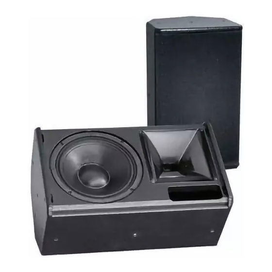
70% permeability, mounted with 4 screws, exchangeable black acoustic foam front covering. The CA 1001, with its compact construction, its light weight and high performance capability is eminently suitable for mobile use in the standard version. Its discreet de- sign also makes the CA 1001 suitable for fixed installations. -
Page 8: Instructions For Versions With '100 V' Option
Important − Speakers can be integrated into existing 100 V systems. Connecting Diagram of the 100V Speaker Inputs The 100 V transformer for the CA 1001 has one 300VA tap. The pin connections can be seen below. 300VA transformer 300VA... -
Page 9: Coverage Angles Of The Ca 1001 Speaker
6. Coverage Angles of the CA 1001 Speaker The CA 1001 can be operated in a vertical or horizontal (i.e. as a stage monitor) posi- tion. The coverage pattern of the speaker can be adapted to special needs by a 90°... -
Page 10: Mounting Instructions For Speakers
The following graphics will assist in making a rough estimate as to the distance range of the CA 1001. The graphics only take into consideration the sum of the direct sound and not the influence of the room. Because of this there can, in some cases, be noticeable deviation. -
Page 11: Arrayed Speaker Systems (Cluster)
*If several 90° systems are clustered, unwanted interference effects may appear. As a result, we do not generally recommend clustered configurations of CA 1001 systems. If wide angles are to be covered, we recommend the use of several systems with ro- tated horns in one cluster. -
Page 12: Horn Rotated
User’s Manual CA 1001 7.2.2 Horn rotated Angle 2 Angle 3 Horn Horn Horn Horn rotated rotated rotated rotated Standing speaker Standing speaker Standing speaker Standing speaker A smaller angle 3 Angle 1 results in a smaller vertical coverage angle but increases the sound power level. -
Page 13: Wiring
The speaker is equipped with two parallel Speakon connectors. Make sure that all units are switched off and all controls are turned down before con- necting your CA 1001 systems. − We recommend the use of high-quality speaker cables provided by KLING & FREITAG. -
Page 14: Avoiding Ground Loops
8.2.2 Avoiding Ground Loops If there is a loud humming or buzzing after the CA 1001 System has been connected, then check that a "ground loop" has not been built into the system. Some power am- plifiers and system controllers are equipped with a "Ground Lift"... -
Page 15: Configurations And Connecting Diagrams
Configurations and Connecting Diagrams Operating the Systems without C2 Controller The CA 1001 systems can be used alone or in conjunction with a K&F subwoofer with integrated crossover (e.g. SW 112-XO / SW 115D-XO / SW 115E-XO or SW 118E-XO). -
Page 16: Full-Range Mode & Subwoofer With Crossover (Xo)
‘XO ON’ for this mode of operation: Switch on the subwoofer’s connecting terminal When using the CA 1001 systems in a cluster (speakers in close proximity), reduce the frequencies below 300 Hz by 3-4 dB. (The K&F C2 Controller is equipped with a special filter for this purpose, which can be activated by pressing the "Top-Low Cut"... -
Page 17: Operations With C2 Controller
User’s Manual CA 1001 Operations with C2 Controller By using carefully adjusted filters (EQ) on special system cards for the CA systems, the C2 Controller optimises feedback prevention and the frequency response of the spea- kers. The controller provides optional bass boost in full-range mode, optimisation for cluster operation (Top Low Cut switch), high boost and sub-mono functions. -
Page 18: Full-Range Mode With K&F C2 Controller
When using CA 1001 systems in a cluster (speakers in close proximity) or as a stage monitor, activate the "Top Low Cut" switch on the C2 Controller. -
Page 19: Ca 1001 & Bass With Controller C2 In 2-Way Active Mode
User’s Manual CA 1001 9.2.2 CA 1001 & Bass with Controller C2 in 2-Way Active Mode Recommended combinations of CA 1001 systems with K&F subwoofers in 2-way active mode with C2 Controller: 2 x CA 1001 via C2 Controller with... -
Page 20: Operating The Speakers
Now put a low level signal into the system and check for the correct function of the system. In doing so, all amplifier input controls need to be turned off again. Now turn on the control for the left CA 1001 system and check that the correct signal is coming out of the CA 1001 system. -
Page 21: Crossovers: Wiring Diagram Ca 1001
User’s Manual CA 1001 11. Crossovers: Wiring Diagram CA 1001 LINK FROM XO 1 XO 2 link to XO 2 link to XO 2 XO 1 Pin assignment Speakon NL4 ‘IN’ 1+ 1- 2+ 2- ‘OUT’ parallel with ‘IN’ 12. Touching Up Damage to Paint / Changing the Front Foam Although the PU structured paint used by KLING &... -
Page 22: Technical Specifications Ca 1001
User’s Manual CA 1001 13. Technical Specifications CA 1001 Loudspeaker Design 2-way passive system, bass reflex tuning Frequency range -10 dB 53 Hz - 20 kHz Frequency range ±3 dB 82 Hz - 19 kHz Coverage angles (nominal) 85° x 55° (hor. x vert.) Directivity index (DI) 10 (+1.5/-1) 1.2 kHz - 14 kHz... -
Page 23: Measuring Charts
User’s Manual CA 1001 14. Measuring Charts Frequency response Frequency response Impedance 31.6 3,16 1000 10000 20000 Frequency (Hz) Horizontal Beamwidth Vertical 1000 10000 20000 Frequency (Hz) Directivity 1000 10000 20000 Frequency (Hz) KLING & FREITAG GMBH ©1995 - 2006 Version 3.0, 22.03.2006... - Page 24 User’s Manual CA 1001 Horizontal coverage 180° 150° 120° 90° 60° Attenuation (dB) 30° < 3 0° 3 - 6 -30° 6 - 9 -60° 9 - 12 -90° 12 - 15 -120° 15 - 18 -150° > 18 -180°...
-
Page 25: Dimensions
User’s Manual CA 1001 15. Dimensions KLING & FREITAG GMBH ©1995 - 2006 Version 3.0, 22.03.2006 Page 25 of 27... -
Page 26: Accessories
User’s Manual CA 1001 16. Accessories Adjustable speaker mount CA 1001 U-mount wall / ceiling bracket CA 1001 with undetachable clamping levers Adjustable speaker mount ’Installation’ CA 1001 Mounting adapter TV-spigot adapter TV style clamp TV-spigot Eyebolt M8 x 20 Further information is available in our downloadable catalogue at: www.kling-freitag.de... -
Page 27: Regulations For Disposal
User’s Manual CA 1001 17. Regulations for Disposal 17.1 Germany: It is not allowed to dispose of used electrical equipment as domestic waste. But please do not dispose of them at official collecting points for recycling either! All Kling & Freitag products are plain business-to-business (B2B) products. Disposal of Kling &...
Need help?
Do you have a question about the CA 1001 and is the answer not in the manual?
Questions and answers