Table of Contents
Advertisement
Quick Links
Advertisement
Table of Contents

Related Manuals for KLING & FREITAG PIA M


Summary of Contents for KLING & FREITAG PIA M
- Page 1 EN | VERSION 1.0 | 08/11/2022 USER‘S MANUAL K&F PIA M...
-
Page 3: Table Of Contents
2.1 Intended Use 2.2 System requirements 2.3 Items Included 2.4 Overview of PIA M Parts 2.5 PIA M Dimensions 2.6 PIA M Dimensions (incl. wall mount) 2.7 Technical Specifications 2.8 Measuring Diagrams 2.8.1 Directivity in bass-reflex mode 2.8.2 Directivity in cardioid mode 2.8.3 Bass reflex mode Frequency Response... - Page 4 User‘s Manual K&F PIA M 12.3 All Other Countries 13 EC Declaration of Conformity Page 4 of 38 Version 1.0 ©KLING & FREITAG GMBH...
-
Page 5: Introduction
User's Manual K&F PIA M Introduction Icons Used This icon indicates a risk of injury or death. Not following these instructions may result in seri- WARNUNG ous health problems including potentially fatal injuries. This icon indicates a possibly dangerous situation. Not following these instructions may cause VORSICHT minor injuries or damage. -
Page 6: Product Description
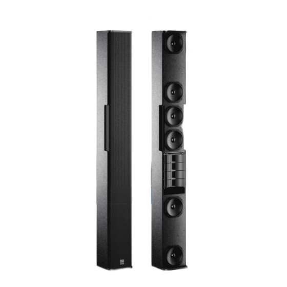
The Kling & Freitag PIA M is a passively isolated 3-way high-performance line-array speaker with variable directivity in the high and low frequency ranges. The PIA M has been designed for mobile use as well as for stationary installations with a focus on superior yet discreet ap- pearance. -
Page 7: System Requirements
User's Manual K&F PIA M System requirements • K&F mounting hardware • K&F SystemAmp: • PLM 20k • PLM 12k • PLM 5k • D200 • D120 • • • • • IPX2400 • IPX1200 • IPD2400 • IPD1200 © KLING & FREITAG GMBH Version 1.0... -
Page 8: Items Included
K&F PIA M PIA M 11.08.2022 08/11/2022 Items Included • 1 x K&F PIA M speaker • 1 x user guide Overview of PIA M Parts M10 bore for fastening mount- ing hardware (same at the top and the base) Cover plates, rotatable by 180°,... -
Page 9: Pia M Dimensions
User's Manual K&F PIA M PIA M Dimensions 79,7 © KLING & FREITAG GMBH Version 1.0 Seite 9 von 38... -
Page 10: Pia M Dimensions (Incl. Wall Mount)
User's Manual K&F PIA M PIA M 11.08.2022 08/11/2022 PIA M Dimensions (incl. wall mount) Version 1.0 © KLING & FREITAG GMBH Seite 10 von 38... -
Page 11: Technical Specifications
User's Manual K&F PIA M Technical Specifications Concept 3-way passive system, active equalization for 1 way Supported amplifiers K&F PLM+ Serie, K&F D Serie, K&F IPX Serie, IPD Serie 85 Hz – 23 kHz, bass reflex FR mode 93 Hz – 22 kHz, bass reflex LCut mode Frequency range @-10 dB 107 Hz –... - Page 12 User's Manual K&F PIA M PIA M 11.08.2022 08/11/2022 RAL 9005 (black) Colors RAL 9010 (white) RAL spot colors available on request 100V option with 50/100/150VA Options Toroidal transformer; wall-mount set Version 1.0 © KLING & FREITAG GMBH Seite 12 von 38...
-
Page 13: Measuring Diagrams
User's Manual K&F PIA M Measuring Diagrams 2.8.1 Directivity in bass-reflex mode Bass reflex mode: Horizontal coverage ‘Narrow’ (5° coverage) 180° 150° 120° 90° 60° Attenuation (dB) 30° < 3 0° 3 - 6 -30° 6 - 9 -60° 9 - 12 -90°... - Page 14 User's Manual K&F PIA M PIA M 11.08.2022 08/11/2022 Bass reflex mode: Horizontal coverage ‘Narrow’ (15° coverage) 180° 150° 120° 90° 60° Attenuation (dB) 30° < 3 0° 3 - 6 -30° 6 - 9 -60° 9 - 12 -90°...
- Page 15 User's Manual K&F PIA M Bass reflex mode: Horizontal coverage ‘Narrow’ (25° coverage) 180° 150° 120° 90° 60° Attenuation (dB) 30° < 3 0° 3 - 6 -30° 6 - 9 -60° 9 - 12 -90° 12 - 15 -120°...
-
Page 16: Directivity In Cardioid Mode
User's Manual K&F PIA M PIA M 11.08.2022 08/11/2022 2.8.2 Directivity in cardioid mode Cardioid mode: Horizontal coverage ‘Narrow’ (5° coverage) 180° 150° 120° 90° 60° Attenuation (dB) 30° < 3 0° 3 - 6 -30° 6 - 9 -60°... - Page 17 User's Manual K&F PIA M Cardioid mode: Horizontal coverage ‘Medium’ (15° coverage) 180° 150° 120° 90° 60° Attenuation (dB) 30° < 3 0° 3 - 6 -30° 6 - 9 -60° 9 - 12 -90° 12 - 15 -120° 15 - 18 -150°...
- Page 18 User's Manual K&F PIA M PIA M 11.08.2022 08/11/2022 Cardioid mode: Horizontal coverage ‘Wide’ (25° coverage) 180° 150° 120° 90° 60° Attenuation (dB) 30° < 3 0° 3 - 6 -30° 6 - 9 -60° 9 - 12 -90° 12 - 15 -120°...
-
Page 19: Bass Reflex Mode Frequency Response
User's Manual K&F PIA M 2.8.3 Bass reflex mode Frequency Response Bass reflex mode, frequency response ‘on axis’ Frequency response FR Frequency response LCut 1000 10000 20000 Frequency (Hz) 2.8.4 Cardioid mode Frequency Response Cardioid mode: frequency response ‘on axis’... -
Page 20: Accessories, Description And Items Included
• 2 x spacers K&F stand sleeve M10 x 30 (incl. mounting material) Allows for mounting the PIA M onto a speaker stand. Included: • 1 x stand sleeve feat. M10×30 thread •... - Page 21 User's Manual K&F PIA M K&F M10×35 eyebolt for suspending a PIA M and for use as a safety eyelet. Color: silver Please remember! TIPP Two M10×35 eyebolts are required for suspending a PIA speaker; this is because you need to fasten the speaker to a second eyebolt for safe- ty purposes.
-
Page 22: General Safety Instructions
Planning must be performed and responsibility be taken by qualified person- nel only. K&F PIA M speakers are to be flown by qualified personnel (riggers) only! Refer to the relevant accessory manuals for safety and handling instructions with regard to your installation options and further details. -
Page 23: Speaker Preparation
User's Manual K&F PIA M Speaker Preparation Adjusting the Vertical Directivity 1. Remove lock pin at the rear panel. 2. Move lever to the desired po- sition. 3. Restore the lock pin to secure the entire setup. 25° 5° 15°... -
Page 24: Selecting Bass-Reflex Or Cardioid Modes
User's Manual K&F PIA M PIA M 11.08.2022 08/11/2022 Selecting Bass-Reflex or Cardioid Modes To select either bass-reflex or cardioid operation, you need to configure both of the rear-panel HINWEIS cardioid-chamber cover plates for the specific operating mode. Doing so will open the bass- reflex or cardioid chambers, respectively. - Page 25 User's Manual K&F PIA M Bass-reflex operation: Cardioid operation: • PIA M BR FR (full range) • PIA M Cardio FR (full range) • PIA M BR LCut (low cut) • PIA M Cardio LCut (low cut) Operating-mode checklist Bass reflex operation...
-
Page 26: Mounting The Accessories
Mounting the PIA M Wall Bracket Risks imposed by falling parts WARNUNG • Be sure to mount the PIA M vertically! • Note you must not install the wall mount at the ceiling. • Before installation, consider the load-bearing capacity, strength, and structure of the wall. - Page 27 User's Manual K&F PIA M 2. Mount the base / top plates sup- plied with the PIA M wall mount as shown. 3. Don’t tighten the M10×50 screw yet—the fastening bracket should still be movable. 4. Repeat the procedure with the second plate.
- Page 28 User's Manual K&F PIA M PIA M 11.08.2022 08/11/2022 5. Install four anchors according to the adjacent drawing [red measurements]. Be sure to leave sufficient space between the anchor head and the wall, so you are able to place the wall mount behind the anchor head.
-
Page 29: Mounting The Pia Mtruss Adapter Set
User's Manual K&F PIA M Mounting the PIA MTruss Adapter Set Required Tools Allen key (size 6) Before mounting the truss adapter, be sure to configure the cardioid cover plate as need- TIPP ed; rotating the cardioid cover plate might not be possible after installation! See chapter »Selecting Bass-Reflex or Cardioid Modes«... -
Page 30: Mounting The Stand Sleeve
User's Manual K&F PIA M PIA M 11.08.2022 08/11/2022 7. Screw the M12 nut with spring washer and washer onto the bolt and tighten 8. Secure the screw connection us- ing butterfly nut [E]. 9. Repeat the procedure to mount the other truss adapter on the opposite side of the speaker. -
Page 31: Mounting The Tv Spigot
User's Manual K&F PIA M Mounting the TV Spigot Required Tools Allen key (size 6) 1. Screw the TV spigot into the M10 thread of the base / top and tighten it. Secure it using the supplied Locktix® lock washer and the O- ring. -
Page 32: Mounting The M10×35 Eyebolt
PIA M. 3. Screw a K&F M10×35 eyebolt into the exposed upper M10 thread on the rear panel. 4. Suspend the PIA M from eyebolt at the top using an approved steel cable or chain suitable for this purpose. -
Page 33: Wiring
User's Manual K&F PIA M Wiring • Before connecting your K&F PIA M speaker, switch off all devices and turn down all faders HINWEIS and encoders. • Be sure to use high-end speaker cables with an appropriate wire gauge. Select the wire size based on the cable length. -
Page 34: Pinout
PIA M 11.08.2022 08/11/2022 Pinout The PIA M speaker has a rear connector panel featuring two recessed SpeakOn ports and one Phoenix terminal all of which are connected in parallel. Initial Operation • Switch off all devices and turn down all volume controls on the mixing console and the HINWEIS amplifiers. -
Page 35: Operation In A Setup With K&F Subwoofers
K&F woofer. We recommend using subwoofers from our K&F NOMOS or K&F PASSIO SUB ranges. Example configurations: 1 x K&F PIA M and • 1 x K&F NOMOS LS2 •... -
Page 36: Transportation And Storage
User's Manual K&F PIA M PIA M 11.08.2022 08/11/2022 Transportation and Storage Store the product in a dry place. Also, transport under dry conditions only. During prolonged storage, ensure sufficient ventilation. Avoid vibrations during transport. Avoid mechanical stress during transport and storage, so the product is not damaged. - Page 37 User's Manual K&F PIA M EC Declaration of Conformity © KLING & FREITAG GMBH Version 1.0 Seite 37 von 38...
- Page 38 THANK CHOOSING K&F. KLING & FREITAG GmbH Junkersstrasse 14 · D-30179 Hannover Phone +49 (0)511 969970 www.kling-freitag.de · info@kling-freitag.de...
Need help?
Do you have a question about the PIA M and is the answer not in the manual?
Questions and answers