
Related Manuals for KLING & FREITAG CA 1001


Summary of Contents for KLING & FREITAG CA 1001
- Page 1 KLING FREITAG CA 1001 & User’s Manual Important Information, Please Read Before Use! KLING FREITAG GmbH & Junkersstrasse 14 D-30179 Hannover PHONE 0 (049) 511- 969 97-0 FAX 0 (049) 511- 67 37 94 www.kling-freitag.de...
-
Page 2: User's Manual Ca
User’s Manual CA 1001 KLING & FREITAG GMBH ©1995-2004 Page 2 of 31... - Page 3 Thank you for your decision to buy a Kling & Freitag product. To guarantee a trouble- free operating of the equipment and to allow the KLING & FREITAG -- - CA 1001 Sys- tem to achieve its full potential please read the operating instructions carefully before use.
-
Page 4: Table Of Contents
Operations with C2 Controller 7.2.1 Full-Range Mode with K&F C2 Controller 7.2.2 CA 1001 & Bass with Controller C2 in 2-Way Active Mode Operating the Speakers Crossovers: Wiring Diagram CA 1001 10. Touching Up Damage to Paint / Changing the Front Foam 11. -
Page 5: General Safety Instructions For Using Speakers
User’s Manual CA 1001 General Safety Instructions for Using Speakers Mounting the speakers To prevent injury, this equipment must be securely placed on the floor or secured to the wall according to the mounting instructions. Speakers, which are stacked, must be se- cured with securing straps. -
Page 6: Product Description And Versions
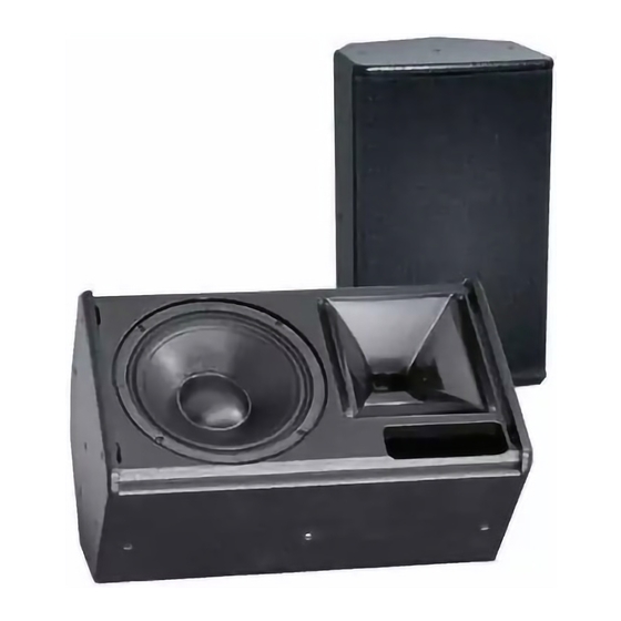
70% permeability, mounted with 4 screws, exchangeable black acoustic foam front covering. The CA 1001, with its compact construction, its light weight and high performance capability is eminently suitable for mobile use in the standard version. Its discreet de- sign also makes the CA 1001 suitable for fixed installations. -
Page 7: Instructions For Suspending The Speakers
We recommend using the M8 threads only for mounting stand adapters and TV-spigot adapters. The M10 threads should be used for mounting the CA 1001 tilt brackets only. Eyebolts can be attached to the M8 and M10 threads in order to suspend the speakers, if they are dimensioned sufficiently (safety factor 12) and are used as described by the manufacturer. -
Page 8: Coverage Angles Of The Ca Speakers
4. Coverage Angles of the CA Speakers The CA 1001 can be operated in a vertical or horizontal (i.e. as a stage monitor) posi- tion. The coverage pattern of the speaker can be adapted to special needs by a 90°... -
Page 9: Mounting Instructions For Speakers
The following graphics will assist in making a rough estimate as to the distance range of the CA 1001. The graphics only take into consideration the sum of the direct sound and not the influence of the room. Because of this there can, in some cases, be noticeable deviation. -
Page 10: Arrayed Speaker Systems (Cluster)
*If several 90° systems are clustered, unwanted interference effects may appear. As a result, we do not generally recommend clustered configurations of CA 1001 systems. If wide angles are to be covered, we recommend the use of several systems with ro- tated horns in one cluster. -
Page 11: Horn Rotated
User’s Manual CA 1001 5.2.2 Horn rotated Angle 2 Angle 3 Horn rotated Standing speaker A smaller angle 3 Angle 1 results in a smaller vertical coverage angle but increases the sound power level. Angle 1 Angle 2 Angle 3 30°... -
Page 12: Wiring
The speaker is equipped with two parallel Speakon connectors. Make sure that all units are switched off and all controls are turned down before con- necting your CA 1001 systems. − We recommend the use of high-quality speaker cables provided by KLING & FREITAG. -
Page 13: Avoiding Ground Loops
6.2.2 Avoiding Ground Loops If there is a loud humming or buzzing after the CA 1001 System has been connected, then check that a "ground loop" has not been built into the system. Some power am- plifiers and system controllers are equipped with a "Ground Lift" switch. Set these swit- ches to the "Lift"... -
Page 14: Configurations And Connecting Diagrams
Configurations and Connecting Diagrams Operating the Systems without C2 Controller The CA 1001 systems can be used alone or in conjunction with a K&F subwoofer with integrated crossover (e.g. SW 112-XO / SW 115D-XO or SW 118E-XO). In this mode of operation the integrated crossover limits the subwoofer's frequency range. -
Page 15: Full-Range Mode & Subwoofer With Crossover (Xo)
Connecting Terminal 1 Connecting Terminal 2 When using the CA 1001 systems in a cluster (speakers in close proximity), reduce the frequencies below 300 Hz by 3-4 dB. (The K&F C2 Controller is equipped with a special filter for this purpose, which can be activated by pressing the "Top Low Cut" switch. -
Page 16: Operations With C2 Controller
User’s Manual CA 1001 Operations with C2 Controller By using carefully adjusted filters (EQ) on special system cards for the CA systems, the C2 Controller optimises feedback prevention and the frequency response of the spea- kers. The controller provides optional bass boost in full-range mode, optimisation for cluster operation (Top Low Cut switch), high boost and sub-mono functions. -
Page 17: Full-Range Mode With K&F C2 Controller
When using CA 1001 systems in a cluster (speakers in close proximity) or as a stage monitor, activate the "Top Low Cut" switch on the C2 Controller. -
Page 18: Ca 1001 & Bass With Controller C2 In 2-Way Active Mode
Recommended combinations of CA 1001 systems with K&F bass systems in 2-way ac- tive mode with C2 Controller: 2 x CA 1001 via C2 Controller with 2 x SW(i) 112 or 2 x SW(i) 115D -- - XO 2 x SW(i) 118E - XO or 1- 2 x SW 215E... -
Page 19: Operating The Speakers
Now put a low level signal into the system and check for the correct function of the system. In doing so, all amplifier input controls need to be turned off again. Now turn on the control for the left CA 1001 system and check that the correct signal is coming out of the CA 1001 system. -
Page 20: Crossovers: Wiring Diagram Ca 1001
User’s Manual CA 1001 Crossovers: Wiring Diagram CA 1001 LINK FROM XO 1 XO 2 link to XO 2 link to XO 2 XO 1 1+ 1- 2+ 2- Pin assignment Speakon NL4 10. Touching Up Damage to Paint / Changing the Front Foam Although the PU structured paint used by KLING &... -
Page 21: Technical Specifications Ca 1001
User’s Manual CA 1001 11. Technical Specifications CA 1001 Design 2-way passive system, bass reflex tuning Frequency range -10 dB 53 Hz - 20 kHz Frequency range ± 3 dB 82 Hz - 19 kHz Coverage angles nominal 85° x 55° (hor. x vert.) Directivity index (DI) 10 (+1.5/-1) 1.2 kHz - 14 kHz... -
Page 22: Measuring Charts Ca 1001
User’s Manual CA 1001 12. Measuring Charts CA 1001 Frequency response ‘on axis’ SPL (dB) Impedance (Ohm) 31,6 3,16 1000 10000 20000 Frequency (Hz) Frequency response 'on axis' with K&F Controller C2 Fullrange 2-Way TopLowCut / Fullrange TopLowCut / 2-Way... - Page 23 User’s Manual CA 1001 Vertical frequency response 'off axis down' 0° 10° 20° 30° 40° 1000 10000 20000 Frequency (Hz) Beamwidth vs. frequency Horizontal Vertical 1000 10000 20000 Frequency (Hz) Q-Index 1000 10000 20000 Frequency (Hz) KLING & FREITAG GMBH ©1995-2004...
- Page 24 User’s Manual CA 1001 Horizontal Polar Diagrams CA 1001 0° 330° 30° 300° 60° 200 Hz 250 Hz ° 270° 315 Hz 400 Hz ° 240° 210° 150° 180° 0° 330° 30° 300° 60° 500 Hz 630 Hz 270° 90°...
- Page 25 User’s Manual CA 1001 0° 330° 30° 300° 60° 3,15 kHz 4 kHz 90° 270° 5 kHz 6,3 kHz 120° 240° 210° 150° 180° 0° 330° 30° 300° 60° 8 kHz 10 kHz 90° 270° 12,5 kHz 16 kHz 120°...
- Page 26 User’s Manual CA 1001 Vertical Polar Diagrams CA 1001 90° 120° 60° 150° 30° 200 Hz 250 Hz 0° 180° 315 Hz 400 Hz 330° 210° 240° 300° 270° 90° 120° 60° 150° 30° 500 Hz 630 Hz 180° 0°...
- Page 27 User’s Manual CA 1001 90° 120° 60° 150° 30° 3,15 kHz 4 kHz 180° 0° 5 kHz 6,3 kHz 330° 210° 240° 300° 270° 90° 120° 60° 150° 30° 8 kHz 10 kHz 0° 180° 12 kHz 16 kHz 330°...
-
Page 28: Important Information For The 'Outdoor Installation' Option
User’s Manual CA 1001 13. Important Information for the 'Outdoor Installation' Option Although the series 'Outdoor Installation' is optimised for outdoor fixed installations, the speakers should not be exposed to direct weather influence like rain or direct sunlight. The version 'Outdoor Installation' differs from the standard version in the following... -
Page 29: Instructions For Versions With 100 V Transformers
− Speakers are galvanically isolated. − Speakers can be integrated into existing 100 V systems. 14.2 Connecting Diagram of the 100V Speaker Inputs The 100 V transformer for the CA 1001 has one 300VA tap. The pin connections can be seen below. 300VA transformer... -
Page 30: Dimensions Ca 1001
User’s Manual CA 1001 15. Dimensions CA 1001 Thread Insert M8 for Mounting Adapter & TV Spigot Adapter Rigging Point Thread Insert M10 99 mm 115 mm Rigging Point [3.898"] [4.528"] Rigging Point Thread Insert M10 Rigging Point Thread Insert M10... -
Page 31: Accessories
User’s Manual CA 1001 16. Accessories Tilt bracket CA 1001 Tilt bracket CA 1001 with undetachable release handles Tilt bracket ’Installation’ CA 1001 Stand adapter TV-spigot adapter Super Clamp TV-spigot Eyebolt M8 x 20 Further information is available in our downloadable catalogue at:: www.kling-freitag.de...
Need help?
Do you have a question about the CA 1001 and is the answer not in the manual?
Questions and answers