Compuprint SP40 User Manual
Hide thumbs
Also See for SP40:
- User manual (65 pages) ,
- Specifications (2 pages) ,
- User manual (57 pages)
Table of Contents
Advertisement
Advertisement
Table of Contents

Related Manuals for Compuprint SP40


Summary of Contents for Compuprint SP40
- Page 1 Rev. 002...
-
Page 2: Compuprint Products Information
Sferal WWT recommends to use only its original Compuprint branded consumables with original packaging (identified by its holographic label). In this way, a proper use of the printer at quality level stated in the product characteristics can be assured. -
Page 3: Fcc Notes
This equipment has been tested and found to comply with the limits for a Class B digital device, pursuant to Part 15 of the FCC Rules. These limits are designed to provide reasonable protection against harmful interference when the equipment is operated in a commercial environment. -
Page 4: Table Of Contents
Compuprint Products Information………………………………….ii Printer Setup ............23 FCC Notes ..................iii Entering the Printer Setup Mode..........23 Canadian D.O.C. Radio Interference Regulation ......iii Printing the Test Page..............24 EEC Regulations ................iii Printing the Printer Setup Forms..........26 Table of ContentsErrore. Il segnalibro non è definito. -
Page 5: Printer Presentation
This dot-matrix printer is a multi-purpose printer for front office applications. Its compact structure is designed for integration in an ergonomic environment. The printer provides a high level of reliability, form-handling accuracy and data integrity. Its main features are: • Printing on a wide range of paper media: different types of cut sheets, multi-parts and passbooks. - Page 6 • Standard parallel and serial interface and automatic switch-over function. • Easy printer setup through an optically managed menu. • Supported emulations: Epson 570, IBM Proprinter XL24E, XL24E AGM, IBM 2390+, 4722, 9068 and Olivetti PR40+, PR2, 2845.
-
Page 7: Unpacking The Printer
Together with the printer the following items are included in the shipment box: Notify any damage to your supplier. • Ribbon cartridge • Power cable • CD-ROM with the printer documentation and drivers. Always keep the packing material in a safe place as you must repack the printer into it, when you need to move it. -
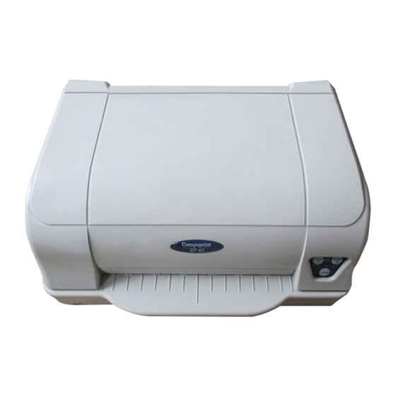
Page 8: Printer Parts
Never remove any printer part unless it is expressly indicated in this manual. Printer Cover Operator Panel Paper Stand Power-on Push-button... -
Page 9: Inside View
Printhead Print Head Assembly Print Area Paper Jam Removal Cog-wheel... -
Page 10: Rear View
Power Cable Connector Serial Interface Cable Connector Parallel Interface Cable Connector... -
Page 11: Printer Installation
Consider the following points when you choose the location for your printer: • The distance between the printer and the host computer must not exceed the length of the interface cable; • The location must be sturdy, horizontal and stable; •... -
Page 12: Installing The Power Cable
1. Find the power cable connector and the rating plate on the rear side of the printer. Always use a grounded outlet. 2. Insert the power cable into the connector on the printer and the other end into a convenient mains outlet. 3. -
Page 13: Installing The Ribbon Cartridge
In order to avoid damaging the print head assembly, this printer accepts only original Compuprint ribbon cartridges. Therefore, if you install a not original cartridge, the printer may not work. 1. Remove the cartridge from its bag. Turn the tension knob in the direction of the arrow to tighten the ribbon. - Page 14 3. Open the print head assembly pushing the two green levers towards the rear of the printer. The print head assembly moves up. 4. Move the print head to the middle of the print carriage bar.
- Page 15 5. Insert the upper cartridge pins (1) onto the corresponding groove on the print head assembly. Then push the lower pin (2) into the corresponding lower groove until it clicks into place.
- Page 16 6. Insert the ribbon mask onto the print head: match the two grooves (1) on both sides of the ribbon mask with the pins (2) on both sides of the print head. 7. Push the mask up until it clicks into place.
- Page 17 8. Turn the tension knob in the direction of the arrow to tighten the ribbon. 9. Push down on the green label “PUSH TO CLOSE” present in the print head assembly until it clicks into place. If you do not close the print-head assembly correctly, the printer does not print and you may damage the printer cover.
-
Page 18: Reset The Ribbon Counter
RESET the Ribbon Counter Two procedures are available for this operation: a) With the printer in Power On, open the cover and, holding all three Operator Panel keys down. b) With the printer in Set up Mode, select the item RIBBON REPLACED = yes (see the PRINTER SETUP section of this manual) -
Page 19: Paper Handling
This printer is designed for versatile and reliable paper handling. The flat-bed mechanism allows the handling of special documents, such as multiple invoices, postcards, labels, passbooks and tickets. The print head detects the paper edges automatically, the sheet can therefore be inserted in any position within the detection area according to the rules described in the following paragraph. - Page 20 • Before inserting a passbook into the printer, open it and crease it in both directions along the binding stitch, so that the passbook lays flat on the paper stand when it is inserted into the printer. • The document may not exceed the limits of the paper stand.
-
Page 21: The Operator Panel
The operator panel is located on the front right side of the printer and is composed of function keys and leds with which you can easily check the printer status and select the functions as described below:... -
Page 22: Function Keys
Pressing this key, when the printer is offline, or when the printer is online and no EJECT print data are in the buffer, the printer ejects the paper, if inserted ( EJECT function). In the Olivetti emulation, the function may be performed only if EJECT the printer is offline. -
Page 23: Leds
On, if the printer is powered on. Off, if the printer is powered off. Blinks if the printer is in Setup Mode. Lit, when the printer is on line. Unlit, when the printer is off line. Blinks, when data are present in the printer buffer and the printer is not ready (offline or paper out condition). -
Page 24: Software Driver Selection
Millennium® environment / 2000 / XP. If you want to install the printer in the Windows environment, insert the CD-ROM and follow the instructions given. The printer drivers of all Compuprint printers can be found at the Internet Address http://www.compuprint.com... -
Page 25: Connection To The Host
This printer can be connected to the host by means of a parallel standard Centronics or bi- directional IEEE 1284 type interface or by means of the serial RS-232/C interface. Proceed as follows: 1. Make sure that both the host and the printer are turned off. 2. -
Page 26: Setting The Interface Parameters
The parameters set for the parallel interface match most of the most common environments and the printer can be used immediately after the connection to the host. In case you need to modify the standard parameters see “Printer Setup” later in this section. Because of the great variety of the possible connection configurations, when you use the serial interface you will need to set the parameters accordingly. -
Page 27: Printer Setup
The Printer Setup is used to configure the printer parameters and to print a Self Test page, to check the settings and the printer installation, and to perform the Print Offset Tuning. The default configuration of this printer matches most of the commonly used environments, but it may be necessary to change some printer parameters. -
Page 28: Printing The Test Page
The printer prints the Self-Test page. Check that the printout is correct. The following printout example shows the Printer Setup default values. Once the self-test is finished, the printer remains in Setup Mode. SP40 Code Version Vx.x xxxxxxxx CharGen:xxxxxxxx ver. x.xx CONFIGURATION SETUP... -
Page 29: Program Setup
PROGRAM SETUP PROGRAM 1 PROGRAM 2 PROTOCOL IBM X24E OLI.PR2 FONT Draft Draft DOWNLINE LOADING enabled enabled HORIZONTAL PITCH 10 lpi 10 lpi VERTICAL PITCH 6 lpi 6 lpi LOCK No lock No lock FORM LENGTH LEFT MARGIN RIGHT MARGIN TOP MARGIN BOTTOM MARGIN IBM C-SET... -
Page 30: Printing The Printer Setup Forms
If you already have the preprinted forms for the printer setup, go to “Filling in the Printer Setup Forms” later in this manual. 1. With the printer in Setup Mode, insert a blank sheet in A4 or Letter format. 2. The printer loads the sheet and stops. 3. - Page 31 The printer setup forms contain all printer parameters and the values that can be set. The current value is indicated by an asterisk (*). For a detailed description of the parameters and the settings see “Setup Parameters” later in this manual.
-
Page 32: Filling In The Printer Setup Forms
To change the values of the parameters, fill in the marker ( ) beside the value you want to set with a black or blue ball-point pen or a fiber-pen. Do not use pencils. AUTOFEED SIGNAL ( ) disabled * enabled SLCT-IN SIGNAL disabled *... -
Page 33: Setup Parameters
The following is a listing of the setup parameters. Configuration Sheet Setup Parameter Values Description RESTORE TO MFG The selected values are not set to factory defaults. The values set in all printer setups are reset to factory default config values. - Page 34 Setup Parameter Values Description automatic type is selected between serial and parallel by the printer depending on data coming from host. *It is reported if the LAN option is installed. For details refer to the LAN manual IBM FINANCIAL Disables the Financial protocol if IBM 4722 or IBM 9068 emulation is selected honorCTS, Enables the IBM FINANCIAL for the IBM 4722 and 9068...
- Page 35 Setup Parameter Values Description none STOP BIT Selects the number of stop bit COPIES no, yes Selects the printing on normal paper (no) or on multicopy format paper (yes) LOW NOISE no, yes Disables/enables the low noise function EDGE DETECTION Normal Detects the left and the right edge of the form Safe...
- Page 36 PROGRAM 1 PROGRAM 2 Setup Parameter Values Description PROTOCOL EPSON 570, IBM X24E, Defines the printer protocol. X24E AGM, IBM 2390, NOTE : For the IBM 4722 and 9068 protocols, if the software driver uses the controlled link of the IBM financial driver, set the IBM OLI.
- Page 37 Setup Parameter Values Description units. See the example below. Example: How to set the form length to 82 lines: FORM LENGTH #lines A4 letter A5 legal 100 x 10 x Setup Parameter Values Description LEFT MARGIN 10 x Sets the left margin in number of columns. The values range between 0 and 90.
- Page 38 hundreds, the second line to the tens and the third line to the units. See the example below: Example: How to set the Right Margin to 101. RIGHT MARGIN 100 x 10 x Setup Parameter Values Description TOP MARGIN 10 x Sets the top margin in number of lines.
- Page 39 Example: How to set the bottom margin to 34 lines: BOTTOM MARGIN 10 x Setup Parameter Values Description IBM C-SET IBM set 1, IBM set 2 Selects the IBM character set. IBM COMPRESS 17.1 cpi, 20 cpi Selects the pitch for the compressed mode printing in IBM emulation.
- Page 40 Setup Parameter Values Description CODE PAGE CP437, CP437G, 96GREEK, CP850, Selects the code page for both the IBM and CP851, CP852, CP853, CP855, CP857, the EPSON emulations. CP858, CP860, CP862, CP863, CP864, CP865, CP866, CP867, CP876, CP877, CP1098, CP1250, CP1251, CP1252, CP1257, GOST, TASS, MAZOWIA, CP437SL, UKRAIN, KOI8-U, 8859/1, 8859/2, 8859/3, 8859/4, 8859/5, 8859/6,...
- Page 41 Setup Parameter Values Description CR=LF+CR If the printer receives a CR code (CR), it performs a carriage return followed by a line feed. If the printer receives a LF code (LF), it performs a line feed. LF=LF+CR If the printer receives a LF code (LF), it performs a line feed followed by a carriage return.
-
Page 42: Offset Adjustments
For a precise adjustment of the position of the printed characters on a preprinted form, the printer allows to easily adjust the first line and the first printing column as follows: 1. When the printer is in Setup Mode, insert a blank sheet into the printer press the key until the leds are lit in the following configuration: 2. - Page 43 OFFSET TUNING SETUP Vertical Position Offset (1/10 INCH) PROGRAM 1 ( ) ( ) ( ) ( ) ( ) ( ) ( )* ( ) ( ) ( ) ( ) ( ) ( ) ( ) ( ) ( ) PROGRAM 2 ( ) ( ) ( ) ( ) ( ) ( ) ( )* ( ) ( ) ( ) ( ) ( ) ( ) ( ) ( ) ( ) Vertical Offset Tuning (1/60 INCH)
- Page 44 The Vertical Offset Tuning values correspond to 1/60 inches and set the vertical offset of the first print line starting from the default standard position at 1 mm from the upper paper margin. The Horizontal Offset Tuning values correspond to 1/60 inches and set the horizontal offset of the first print line starting from the default standard position at 3 mm from the left paper margin.
-
Page 45: Reading The Preprinted Forms
When the Printer Setup Forms have been filled in, insert them back into the printer, when the printer is in Setup Mode. The printer is able to recognize the Setup Forms by means of the markers on these pages. The printer reads the values marked for the various parameters and configures the printer accordingly. -
Page 46: Printer Setup Overview
ON-OFF – Printer ready LINE LINE Setup Mode Printer OFF Parameters are set EJECT ON-OFF LINE EJECT EJECT ON-OFF LINE EJECT EJECT ON-OFF LINE EJECT EJECT ON-OFF LINE EJECT... -
Page 47: Troubleshooting
The straight paper path of this printer is designed for trouble-free handling of a great variety of documents. In case a paper jam condition occurs, proceed as follows: 1. Open the printer cover. 2. Open the print-head assembly pushing the green levers towards the rear of the printer. The print-head assembly moves up. - Page 48 3. Remove the jammed paper, pulling it towards the front of the printer. 4. In case it is not possible to remove the jammed paper because you cannot reach it with your hand or it is embedded so that you cannot move it, rotate the cog-wheel beside the paper path lever to free the paper.
-
Page 49: Paper Damaged After Printing
5. Push down on the green label “PUSH TO CLOSE” present in the print head assembly until it clicks into place. If you do not close the print-head assembly correctly, the printer does not print and you may damage the printer cover. 6. -
Page 50: Ribbon Cartridge Problems
Change the ribbon cartridge. The printer does not The ribbon cartridge is not an The printer checks the inserted cartridge, to print original Compuprint cartridge. avoid damaging the print head assembly due to incorrect ribbon feeding. Insert an original Compuprint ribbon cartridge. -
Page 51: Paper Specifications
The documents must all guarantee the following characteristics: • Use paper matching the indicated characteristics. • They must have well defined top and left edges, with a square angle tolerance of 0.1° on all edges. • The paper must not have holes, perforations, folds or tears anywhere within the print area of the document. -
Page 52: Cuts Sheets
Insertion direction Print Area Dimensions Maximum Minimum Form width 244 mm 65 mm Form length 470 mm 70 mm Distance between dot 3.0 mm position and left or right paper edge Distance between top of the 1 mm first printed line and top margin of the document Distance between the lower 6.6 mm... -
Page 53: Passbooks
Minimum Maximum 120 g/m Paper Weight Thickness Multiple Page Passbooks Horizontal Fold 0.28 mm (0.011 in.) 1.80 mm (0.071 in.) Thickness difference across the fold of an open passbook Horizontal Fold 1.52 mm (0.059 in.) Vertical Fold 1.52 mm (0.059 in.) Single Page Passbook or Ledger Cards 0.18 mm (0.0071 in.) 0.28 mm (0.011 in.) -
Page 54: Passbooks With Horizontal Fold
Dimension Maximum Minimum Passbook width 241 mm 110 mm Insertion direction Passbook length 220 mm 130 mm Distance between print 3.0 mm character position and left or right edge Distance between top 1 mm Print Area edge of the document and top edge of first printed line Distance between... - Page 55 Passbook width 241 mm 110 mm Passbook length 220 mm 85 mm Distance for the dot 3,0 mm position nearest to the left or right edge Distance from the top 1 mm edge of the document to the top edge of the first printed line Distance from the bottom 6,6 mm...
-
Page 56: Technical Specifications
Printing Technology Print head: ER24S 24 pin – Ø 0,25 mm Print head life 400 million characters Resolution: 360 x 360 dpi (HxV) Line Length (@ 10 cpi) 94 columns (cut sheets) Printing Speed 400 cps @ 10 cpi (Draft) 133 cps @ 10 cpi (LQ) Emulation IBM ®... - Page 57 Character Sets (OLIVETTI protocols) CS000 – CS010 International, CS020 Germany, CS030 Portugal, CS040 Spain1, CS050 Denmark/Norway, CS060 France, CS070 Italy, CS080 Sweden/Finland, CS090 Switzerland, CS100 Great Britain, CS110 USA ASCII, CS140 Greece, CS150 Israel, CS170 Spain 2, CS200 Jugoslavia, CS410 Olivetti TCV 370, CS510 SDC, CS520 Turkey, CS540 CIBC, CS680 OLI-UNIX, CS701 PC-220 Spain2, CS711 PC-Denmark/Norway, CS712 PC-Denmark OPE, CS771 PC-210 Greek Barcodes...
- Page 58 Ribbon Life 4 million characters (black) Reliability MTBF: 10,000 hours Duty cycle 28000 pages/month Physical Dimensions & Weight 400 (W) x 295 (H) x 200 (D) mm < 12 Kg Power Supply Type Universal - autoswitching Power consumption: < 60 W (printing ISO/IEC 10561) Environmental conditions Temperature: working +10 to +40 °C...
-
Page 59: Msrw - Micr Addendum
MSRW – MICR ADDENDUM _____________________________________________________________________________________________________________-... - Page 60 MAGNETIC STRIP READER/WRITER The horizontal magnetic strip reader/writer is used to read and write data on the magnetic stripe of bank passbooks. Magnetic stripe has to be placed horizontally on the booklets, according to the print line direction, to be properly managed by the magnetic option. Here below are reported the device specifications for details.
- Page 61 Recordable characters 0-9 and “E” Recording direction Left to Right Center of vertical position 13,9 mm Horizontal start position 9.5 mm. from the left edge Recordable characters number 45 max with field duplication Recording capacity 108 char. Max (control codes and separator included) ANSI standard Bit density 210 Bit Per Inch ±...
- Page 62 Bourroughs standard Bit density 161, 210 Bit Per Inch ± 5% Preamble 25 “zero” bits Postamble 25 “zero” bits Start sentinel (SOM) End sentinel (EOM) Recordable characters 0-9 and “E” Recording direction Left to Right Center of vertical position 12,01 mm Horizontal start position 15 mm.
- Page 63 B-05...
- Page 64 B-06...
- Page 65 Bourroughs standard lay-out B-07...
- Page 66 MAGNETIC INK CHARACTER RECOGNITION B-08...
- Page 67 The horizontal MICR option is used to read and decode bank cheque code-line. Herebelow are reported detailed specifications. Standards supported: CMC7 and E13B Reading speed: 0.7 m/sec. (27 ips) Character recognition throughput: CMC7: 0.9 sec. E13B: 4 sec. Missed recognition error rate CMC7 1/10.000 characters E13B...
- Page 68 B-010...
- Page 69 PRINTER SET UP Following the “printing self test” instructions reported on the user manual, the printer status page obtained reports also the actual settings for magnetic strip reader device. Printing the setup forms and then filling the selected configuration choice box, according to the user manual instructions, it is possible to change the magnetic strip reader configuration.
- Page 70 The configuration setup page reports all the possible selectable choices. To print configuration setup page see the Printer Setup section of this manual. Setup parameter Values Description MSRW STANDARD IBM3604 Magnetic stripe standard selection DIN32744 ANSI BURR. 1 BURR. 2 END SENTINEL End sentinel symbol, valid only for IBM3604 DISPLACEMENT...
- Page 71 DUAL COLOR SCANNER The dual scanner is located at the rear of the printer. The paper alignment sensors provide to align the paper and adjust it if necessary. The print detects the paper edges automatically, the sheet can therefore be inserted in any position within the detection area according to the rules described at page 15 of this document.
- Page 72 “SFERAL WWT LS A4 USB”,select “Install from a list specific location (Advanced)” and click “Next” to continue . 5. Push Browse Button and select on Compuprint CD the path : Source\drivers\Compuprint SP40\USB\Driver” 6. Then follow the instructions up to the end of installation software.
Need help?
Do you have a question about the SP40 and is the answer not in the manual?
Questions and answers