Advertisement
Quick Links
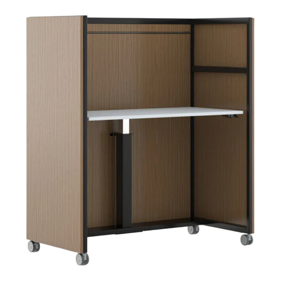
Kore
®
Mobile Workstation - Adjustable Height Surface
Tools Required
• 4mm hex bit
• #2 Phillips bit
• 6mm hex bit
• Drill or impact driver
• Tape Measure
• 3mm hex bit
Installation
1.
Unpack all components.
2.
Assemble metal frame by placing Left Frame on
clean soft surface. Slide the Connector Rail over the
upper "U" bracket and secure with 2 M5 Flathead
screws. See Figure A.
3.
Slide Lower Horizontal Weldment over lower Brack-
ets but do not install the screws at this time. See Figure
A.
4.
Place the Right Frame assembly on top of assembly
and secure in place with remaining 2- M5 Flathead
screws into the connector rail. The screws holding the
Lower Horizontal Weldment will be installed after the
back panel has been installed. See Figure A.
5.
Install back panel by first flipping the cart assembly
on its front as seen in Figure B. Place a supplied spring
and wood dowel in each slide of the back panel. Slide
the dowels on the top of the back panels into the oblong
holes on the Connector Rail. Compress the springs on
the sides by pressing the dowels into the holes while
pivoting the back panel into place until the bottom of the
back panel is seated securely on the Lower Horizontal
Weldment. Without the screws in place, the Lower Hori-
zontal Weldment should slide down and provide room to
insert the back panel.
6.
The spring should push the side dowels into the
mating oblong holes on the frame and you should here a
"Click". Secure the bottom of the back panel to the Low-
er Horizontal Rail with the supplied #8 -1" wood screws.
Secure the Lower Horizontal Weldment with the 8- M5
Button head cap screws.
Tip: Ensure any loose felt is completely tucked into
seam by pushing it into seam using a plastic card.
7.
Lay the cart on its back to install the Height Adjust
Column. Slide the Column Bracket over the Height Ad-
just Column with the flange down then insert the Height
Adjust Column into the square cutout in the Lower Hori-
zontal Weldment. Attach the Height Adjust Column to
the Lower Horizontal Weldment using the supplied M8
Cap Screws.
Part 3139104,D
Hardware
•
4 - M5 X 8 Flat Head Cap Screws
•
8 - M5 X 8 Button Head Cap Screws
•
4 - M8 X 25 Cap Screws
•
25 - #10 x 7/8" Phillips Woodscrew
Figure A
Figure B
Proper product installation, in accordance with these instructions, is the responsibility of the installing agent.
If you have any questions concerning these instructions, please call Kimball Customer Care.
Assembly Instructions
•
2 - Black Wood Dowels
•
2 - Springs
•
6 - #8 X 1" Wood Screws
•
2 - #8 x 5/8" Phillips Woodscrew
Column Bracket
(Flange down)
Install before
attaching
column.
Height Adjust
Column
1
Advertisement

Subscribe to Our Youtube Channel
Related Manuals for Kimball Kore


Summary of Contents for Kimball Kore
- Page 1 Lower Horizontal Weldment using the supplied M8 Cap Screws. Proper product installation, in accordance with these instructions, is the responsibility of the installing agent. If you have any questions concerning these instructions, please call Kimball Customer Care. Part 3139104,D...
- Page 2 Ensure casters track smoothly on intended surface. Figure E Figure D Column Handle Proper product installation, in accordance with these instructions, is the responsibility of the installing agent. If you have any questions concerning these instructions, please call Kimball Customer Care. Part 3139104,D...
Need help?
Do you have a question about the Kore and is the answer not in the manual?
Questions and answers