Table of Contents
Advertisement
Quick Links
BT9340-fm
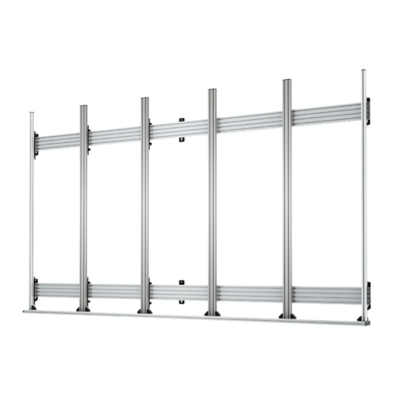
Universal DVLED Videowall Mount
for front mounted dvled cabinets
INSTALLATION GUIDE
SPECIFICATIONS
• Universal mounting solution suitable for a variety
of DVLED cabinets and configurations
• Designed for front mounted DVLED cabinets
• Open frame allows panel access for easy servicing
and maintenance
• Pre-assembly of major parts for quick and easy installation
• All mounting hardware included
• For indoor use only
www.btechavmounts.com
Advertisement
Table of Contents

Subscribe to Our Youtube Channel
Related Manuals for B-Tech BT9340-FM


Summary of Contents for B-Tech BT9340-FM
- Page 1 BT9340-fm Universal DVLED Videowall Mount for front mounted dvled cabinets INSTALLATION GUIDE SPECIFICATIONS • Universal mounting solution suitable for a variety of DVLED cabinets and configurations • Designed for front mounted DVLED cabinets • Open frame allows panel access for easy servicing and maintenance •...
-
Page 2: Installation Safety Instructions
Please check carefully to make sure there are no missing or defective parts - defective parts must never be used. B-Tech AV Mounts, its distributors and dealers are not liable or responsible for damage or injury caused by improper installation, improper use or failure to observe these safety instructions. In such cases, all guarantees will expire. -
Page 4: Wall Mount
BT9340-fm PARTS LIST PLEASE KEEP THIS FOR FUTURE REFERENCE Note: Images for reference only as sizes may differ depending on installation type WALL MOUNT ALTERNATIVE HORIZONTAL MOUNTING RAIL WALL PLATES BT8390-WFK1 BT8390-WFK2 BT8390-WFK3 BT8390-WFK5 Wall mount assembly example INTERFACE ARMS... - Page 5 B-Tech International Design and Manufacturing Limited makes every effort to provide accurate information, however DIMENSIONS ARE there is no guarantee or representation to the user as to the accuracy, currency, suitability or reliability of this data. The user assumes all risks associated with its use. B-Tech IN MILLIMETERS...
-
Page 6: Installation Instructions
INSTALLATION INSTRUCTIONS OPTIONAL EXTEND MOUNTING RAILS Connect items B1* together using item G1 and tighten grub screws, combining the rails securely. Repeat this procedure for the both rails. *Note: Item B1 may be supplied in different lengths. Refer to the installation drawing for guidance on rail assembly. - Page 7 FIX MOUNTING RAILS TO THE WALL Keyhole mounting - Using a BT8390-WFK5 Adjustable Depth Wall Plate i. Use the installation drawing (item H1) to mark and drill the fixing holes for each item A1 assembled on item B1, starting with the bottom rail. ii.
- Page 8 iv. Refer to the installation drawing (item H1) to position and fix the remaining rails (item B1). ADJUST RAILS TO ALIGN* v. Use a plumb line, spirit level and the depth adjustment screws on item A1 to align rails vertically and horizontally. DEPTH ADJUSTMENT SCREW Note: Use adjustment guides...
- Page 9 OPTIONAL EXTEND INTERFACE ARMS Combine items D1 together using items G1. Repeat this procedure for items D2/D3. Extending items D2/D3. OPTIONAL EXTEND BOTTOM ROW LEDGE Combine items C1 together using items G1. Bottom Row Ledge Top View FRONT BACK FRONT 4th channel 2nd channel...
-
Page 10: Installation Drawing
ATTACH VERTICAL INTERFACE ARMS TO BOTTOM ROW LEDGE i. Starting from the left of the bottom row ledge (item C1), INTERFACE ARMS FRONT VIEW insert 1 x item D5 into the 1st channel and 1 x item D5 into the 2nd channel. Position and fix in place item D3 using items D4 &... -
Page 11: Front View
ii. Use item F1 as a template to position the first middle arm (item D1). Insert 2x item D5 into the 2nd channel of item C1. Secure item D1 in place using items D4 & D5. MIDDLE ARM FRONT VIEW iii. - Page 12 HOOK VERTICAL INTERFACE ARMS ONTO THE MOUNTING RAILS i. Hook items D1, D2, D3 & C1 onto items B1. ii. Semi-fix items D1, D2 & D3 on item B1 by tightening the safety screws on the bottom of the hook arms. Do not fully tighten until dvLED cabinets have been mounted.
- Page 13 MOUNT DVLED CABINETS ONTO INTERFACE ARMS i. Insert 2 x items E2 into item D1 right slot and 2 x items E2 into item D1 left slot, approximately. where the dvLED cabinet fixing holes will be located. LEFT SLOT RIGHT SLOT (if applicable) (if applicable) ii.
- Page 14 iv. Repeat the previous steps to mount each dvLED chassis until the desired width is achieved. v. Fully tighten all items E1. vi. Repeat the previous steps to mount the next row of dvLED chassis, until the desired height is achieved. Note: Refer to the dvLED cabinet manufactuer's manual on how to fix the cabinets together and how to connect the power/data cables.
- Page 15 ADD END CAPS AND TIGHTEN SAFETY SCREWS i. Once all the power/data cables are connected and the DVLED modules are mounted onto the dvLED chassis, clip items B2 onto the end of items B1. ii. With a knife, cut to length 1x items C3 and insert all into the front of item C1 and add item C2 to end of the ledge.
- Page 16 ©2021B-Tech International Design and Manufacturing Ltd. All rights reserved. B-Tech AV Mounts is a division of B-Tech International Design and Manufacturing Ltd. B-Tech AV Mounts and the B-Tech logo are registered trade marks. All other brands and product names are trademarks of their respective owners.
Need help?
Do you have a question about the BT9340-FM and is the answer not in the manual?
Questions and answers