Advertisement
Quick Links
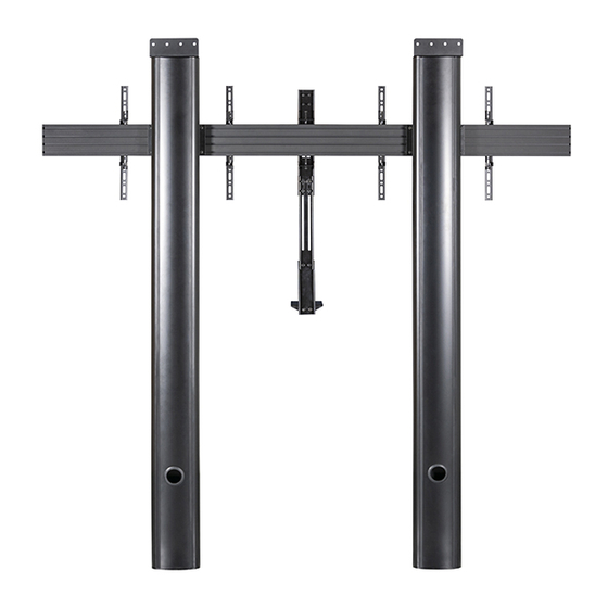
BT8710
PREMIUM FLOOR-TO-WALL
TWIN SCREEN VC STAND
INSTALLATION GUIDE
SPECIFICATIONS
• Recommended for screens: 46" - 65" (117 - 165cm)
• Max load: 70kg (154lbs) per screen
• Suitable for displays with fixings up to 600 x 400mm
• Stand dimensions: H.1969 x W.2005 x D.165mm
• Integrated cable management
www.btechavmounts.com
65"
165
CM
PER SCREEN
Advertisement

Related Manuals for B-Tech BT8710


Summary of Contents for B-Tech BT8710
- Page 1 BT8710 PREMIUM FLOOR-TO-WALL TWIN SCREEN VC STAND INSTALLATION GUIDE SPECIFICATIONS • Recommended for screens: 46" - 65" (117 - 165cm) • Max load: 70kg (154lbs) per screen • Suitable for displays with fixings up to 600 x 400mm 65" • Stand dimensions: H.1969 x W.2005 x D.165mm •...
- Page 2 Please check carefully to make sure there are no missing or defective parts - defective parts must never be used. B-Tech AV Mounts, its distributors and dealers are not liable or responsible for damage or injury caused by improper installation, improper use or failure to observe these safety instructions. In such cases, all guarantees will expire.
- Page 4 BT8710 PARTS LIST NOT REQUIRED PLEASE KEEP THIS FOR FUTURE REFERENCE INSTALLATION TOOLS REQUIRED Drill 10mm Masonry Pencil Spanner Crosshead Screwdriver Pliers/Cutter Drill bit...
- Page 5 ITEM PART REF DESCRIPTION 1.9M COLUMN END CAP COLUMN REAR COVER M6 x 12mm HEX SCREW M6 x 12mm GRUB SCREW (OPTIONAL) SQUARE NUT (OPTIONAL) COVER STRIP 3AF HEX KEY 4AF HEX KEY WALL PLATE BASE PLATE M6 x 12mm SCREW M8 x 50mm COACH SCREW N°.10 x 50mm WALL PLUG M8 T1.5mm METAL WASHER...
- Page 6 Installation Instructions ATTACH MOUNTING BRACKETS TO COLUMNS i. Insert 4 x item C2 into item C1 and attach item C3. Screw two full turns to leave item C3 at the end of item C2. M6 x 40mm RECTANGLE CSK HEX SCREW ii.
-
Page 7: Top View
ATTACH WALL PLATES TO COLUMNS Fix item B1 to the top of item A1 using item B3. M6 x 12mm HEX SCREW FIX FLOOR PLATES TO FLOOR TOP VIEW 60mm Fix item B2 to floor (fixings not included). Note: Fixing points are 60mm away from the wall and 06.5mm the floor plates should be set 600mm apart. - Page 8 MARK WALL FIXING HOLES Using the guide pins, place item A1 onto item B2. Mark the 4 fixing holes from item B1 onto the wall for each column. GUIDE PINS...
- Page 9 DRILL HOLES AND INSERT WALL PLUGS Remove item A1 and drill marked holes. Insert 4 x item B6 for each column (Not required for wood/stud walls). MASONARY WALL 10mm Masonary Drill Bit...
- Page 10 HOOK RAIL ONTO MOUNTING BRACKETS i. Insert 4 x item C4 into item D1 (2 in the top channel, 2 in the bottom channel) on each side of the rail. M8 SLIDING M8 x 12mm ii. Screw 2 x item C5 into item C4 in the top channel - allow at least a 6mm gap HEX SCREW INSERT so the rail can be hooked on to item C1.
- Page 11 FIX COLUMN TO WALL i. Place item A1 onto item B2.
- Page 12 ii. Fix item B1 to the wall using items B4 & B5. iii. Attach item D2 to the ends of items D1.
- Page 13 ASSEMBLE VC SHELF i. Attach item G2 to item G1 using items G5 & G6. ii. Attach item G10 to item G2. using items G7 & G8. M8 x16mm M8 NYLOC M8 METAL M8 SPRING WASHER HEX SCREW WASHER 13mm Spanner Note: The shelf adaptor can mount the shelf above or below the screens.
- Page 14 HOOK SHELF ONTO MOUNTING RAIL i. Hook item G1 onto item D1. ii. Secure shelf to rail. Use item G4 on the bottom of item G1 to secure the shelf to item D1. Optional: Level the shelf bracket by adjusting item G4 on top of item G1.
- Page 15 ATTACH INTERFACE ARMS TO SCREENS Fix item E1 to the rear of the screens using items E3 - E15. Note: Ensure the arms are facing the correct way round and the same holes are used on all arms. E3-E11 SCREEN 13mm SPACER Note: 13mm spacers are not required if the VC shelf is not being installed or if reverse mounting...
- Page 16 HOOK SCREENS ONTO RAIL Use items E1 to hook the screens onto item D1. SCREEN SCREEN LOCK SCREENS TO RAIL Tighten the safety screws on the bottom of item E1 securing the screens to item D1. Optional: Note: If necessary, adjust the height adjustment HEIGHT ADJUSTMENT screws on top of item E1 to level the screen.
- Page 17 ATTACH CAMERA TO SHELF Fix camera to item G10 using M4 x 10mm UNC 1/4” x 1/2” either item G11 or item G12. SCREW SCREW VC CAMERA G11 G12 ATTACH STRIPS Insert item A7 to the front and back of item A1. Note: Item A7 may have to be cut down to size to be able to fit into the front of item A1.
-
Page 18: Front View
PLEASE KEEP THIS FOR FUTURE REFERENCE FRONT VIEW 180mm 8.4mm 60.8mm BOTTOM VIEW 51mm 6.5mm 66mm 150mm These instructions are intended as a guide only and B-Tech accepts no liability for the accuracy of the information contained in this document. -
Page 19: Side View
REAR VIEW 50mm 400.1mm 50mm 159mm 50mm 15mm 8.5mm 20.5mm 253.1mm 60.8mm TOP VIEW 2005mm 90mm 51mm 100mm These instructions are intended as a guide only and B-Tech accepts no liability for the accuracy of the information contained in this document. - Page 20 ©2020 B-Tech AV Mounts. All rights reserved. B-Tech AV Mounts is a division of B-Tech International Design and Manufacturing Ltd. B-Tech AV Mounts and the B-Tech logo are registered trade marks. All other brands and product names are trademarks of their respective owners.
Need help?
Do you have a question about the BT8710 and is the answer not in the manual?
Questions and answers