Advertisement
Quick Links
BT8340
UNIVERSAL
VIDEOWALL MOUNTING SYSTEM
INSTALLATION GUIDE
SPECIFICATIONS
• Recommended screen size: 32"- 70"
• Max weight per screen: 50kg (110lbs)
• Suitable for landscape or portrait mounting
• Sections can be joined together to increase video wall width
• Safety screws help prevent unauthorised removal of screens
• All mounting hardware included
Note: This assembly manual covers di erent installations. Some
parts or procedures shown may not be required for installation.
Please refer to page 5
for VESA® xings
www.btechavmounts.com
TM
PER SCREEN
Advertisement

Related Manuals for B-Tech SYSTEM X BT8340


Summary of Contents for B-Tech SYSTEM X BT8340
- Page 1 BT8340 UNIVERSAL VIDEOWALL MOUNTING SYSTEM INSTALLATION GUIDE SPECIFICATIONS • Recommended screen size: 32”- 70" • Max weight per screen: 50kg (110lbs) • Suitable for landscape or portrait mounting • Sections can be joined together to increase video wall width • Safety screws help prevent unauthorised removal of screens •...
- Page 2 It is recommended that periodic inspections of the product and its xing points are made as frequently as possible (no more than 6 months apart) to ensure that safety is maintained. B-Tech AV Mounts recommends that a suitably quali ed person is used for the removal of this product.
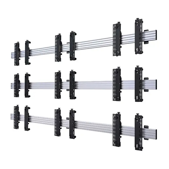
- Page 4 BT8340 PARTS LIST Due to the multiple installations available the quantity for each option below is dependent on the mount ordered. All these components can be moved or carried by manpower. Please be careful to avoid injury when PLEASE KEEP THIS FOR FUTURE REFERENCE handling these components before &...
- Page 5 Screen Interface Arms INTERFACE KIT BT8390-VESA200F BT8390-VESA200T BT8390-VESA400MAF VESA 200mm VESA 200mm VESA 400mm BT8390-VESA400T VESA 400mm VESA 400mm ITEM PART NAME PER PACK SCREEN INTERFACE ARM - LEFT SCREEN INTERFACE ARM - RIGHT M6 x 8mm HEX SCREW** 4AF HEX KEY** 5AF LONG HEX KEY SCREEN FIXING KIT M4 x 12mm SCREW*...
-
Page 6: Typical Installations
TYPICAL INSTALLATIONS 2 x 2 Videowall Installation with VESA 400 Micro-Adjustment Arms INSTALLATION TOOLS REQUIRED Drill Pencil 10mm (7/16”) masonry bit or 4mm (5/32”) wood bit Crosshead Stud Finder screwdriver (Optional) Level (Optional) 3 x 3 Videowall installation with VESA 400 Micro-Adjustment Arms BT8390-150 BT8390-EXT BT8390-WFK1... - Page 7 OPTIONAL EXTENDING THE mounting rail COMBINING MOUNTING RAILS i. On one side of item B1, insert 4x item C1 half-way into each channel. ii a. Using BT8390-WFK1. On the back side of item B1, insert 1x item C1 in the second channel and 1 x item C1 in the third channel - See Fig.
-
Page 8: Installation Instructions
INSTALLATION INSTRUCTIONS INSERT M8 SLIDING NUTS INTO MOUNTING RAIL a i. BT8390-WFK1 assembly - For each item A1 used, insert 2x item A4 into item B1. 1 in the top channel and 1 in the bottom channel. b i. BT8390-WFK2 assembly - For each item A1 used, insert 4x item A4 into the item B1. 2 in the second from top channel and 2 in the bottom channel. - Page 9 BT8390-WFK1 ATTACH WALL FIXING KIT TO MOUNTING RAIL a ii. Attach item A1 to item B1 by fastening item A5 into item A4. BT8390-WFK1 BT8390-WFK1 BT8390-WFK2 Required quantity of Rail Fixing Brackets (item A1) 2pcs for 0 - 2000mm (0 - 79") 3pcs for 2100mm - 3500mm (80"...
-
Page 10: Installing The Mount
INSTALLING THE MOUNT i. Determine the centre of the rst screen at the bottom left. Mark the centre, for the centre of the rail. WALL ii. Mark and drill two xing holes for each item A1 assembled. Insert item A3 and the top item A2. Do not fully tighten - Allow a gap (approx.10mm). - Page 11 ATTACH INTERFACE ARMS TO SCREEN Fix items D1 & D2 to the rear of the screen using items A-M. Note: Ensure the arms are A. FIXED ARMS facing the correct way round and the same holes are used on both arms. SCREEN FIXING KIT SCREEN...
- Page 12 C. MICRO-ADJUSTMENT ARMS Fix items D1 & D2 to the rear of the screen using items D-N. Note: Ensure the arms are facing the correct way SCREEN FIXING KIT round and the same holes are used on both arms. Use spacers for screens with recessed xings SCREEN SCREEN OPTIONAL ADAPTOR ARMS...
- Page 13 HOOK SCREEN ONTO RAIL i. Hook the rst screen onto the centre of the bottom rail and make sure the screen is aligned with the centre of item B1. WALL Y AXIS KNOB Z AXIS KNOB Z AXIS KNOB Note: Micro-adjustment of screens only available using BT8390-VESA400MAF interface arms, for screen levelling on Fixed and Tilt arms - see page 15.
- Page 14 HOOK THE REMAINING SCREENS ONTO RAILS Starting from the bottom rail, hook the remaining screens onto rails using a plumb to align. After mounting each screen use the Y & Z micro-adjustment knobs on the interface arms* items D1 & D2 to level and align screens. Note: A 1mm gap between screens should be maintained.
- Page 15 SECURE INTERFACE ARMS TO THE RAIL Once screens are aligned tighten the safety screws on items D1 & D2, securing the arms to the rail. SCREEN SAFETY SCREW Tightened into item B1. SAFETY SCREW SECURE SCREENS (FIXED AND TILT ARMS*) i.
- Page 16 Distance from wall 86.1mm Distance from wall 99.1mm (Tolerance 1mm) (Tolerance 1mm) +/-10mm Depth Adjustment +/-10mm Depth Adjustment THESE INSTRUCTIONS ARE INTENDED AS A GUIDE ONLY AND B-TECH ACCEPTS NO LIABILITY FOR THE ACCURACY OF THE INFORMATION CONTAINED IN THIS DOCUMENT.
- Page 17 Fixed VESA 400mm Interface Arms VESA 400mm Interface Arms with Tilt 20° 45.2mm 75mm 15° 10° 28mm 40mm THESE INSTRUCTIONS ARE INTENDED AS A GUIDE ONLY AND B-TECH ACCEPTS NO LIABILITY FOR THE ACCURACY OF THE INFORMATION CONTAINED IN THIS DOCUMENT.
- Page 18 2 x Ø 8.4mm 24mm 24mm 4 x Ø 9.3mm FRONT VIEW REAR VIEW SIDE VIEW FRONT VIEW SIDE VIEW THESE INSTRUCTIONS ARE INTENDED AS A GUIDE ONLY AND B-TECH ACCEPTS NO LIABILITY FOR THE ACCURACY OF THE INFORMATION CONTAINED IN THIS DOCUMENT.
-
Page 19: Mounting Rails
500mm 705mm 505mm BT8390-150 1500mm 1505mm BT8390-175 1750mm 1755mm BT8390-200 2000mm 2005mm 30mm 30mm 8.2mm 30mm 30mm THESE INSTRUCTIONS ARE INTENDED AS A GUIDE ONLY AND B-TECH ACCEPTS NO LIABILITY FOR THE ACCURACY OF THE INFORMATION CONTAINED IN THIS DOCUMENT. - Page 20 ©2021 B-Tech International Design and Manufacturing Ltd. All rights reserved. B-Tech AV Mounts is a division of B-Tech International Design and Manufacturing Ltd. B-Tech AV Mounts and the B-Tech logo are registered trade marks. All other brands and product names are trademarks of their respective owners.
Need help?
Do you have a question about the SYSTEM X BT8340 and is the answer not in the manual?
Questions and answers